Engines Iveco C87 / Cursor 87. Manual - part 18
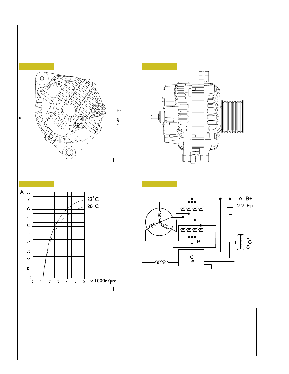
Figure 20
Alternator
Supplier
MITSUBISHI
Technical features
24V - 90A
Figure 21
Figure 22
Figure 23
116714
116713
116716
116715
44
SECTION 3 - INDUSTRIAL APPLICATION
F2C CURSOR ENGINES
Base - June 2006
Description
S
+ 30
L
Battery recharge light
B-
Negative
B+
Positive
IG
+ 15