Isuzu Amigo / Axiom / Trooper / Rodeo / VehiCross. Manual - part 30
 

  Index      Isuzu     Isuzu Amigo / Axiom / Trooper / Rodeo / VehiCross - service repair manual 1999-2002 year


Search            


Content   ..  28  29  30  31   ..


Isuzu Amigo / Axiom / Trooper / Rodeo / VehiCross. Manual - part 30


HEATING, VENTILATION AND AIR CONDITIONING (HVAC) 1A–91

Troubleshooting With Self-Diagnosis Function

Overview of Self-Diagnosis Function

Sensors (input) and actuators (output) are used to check
circuit function and provide essential data on these
circuits. For more detailed information, refer to the
[Inspection and Repair] Sections for the applicable
system or component.
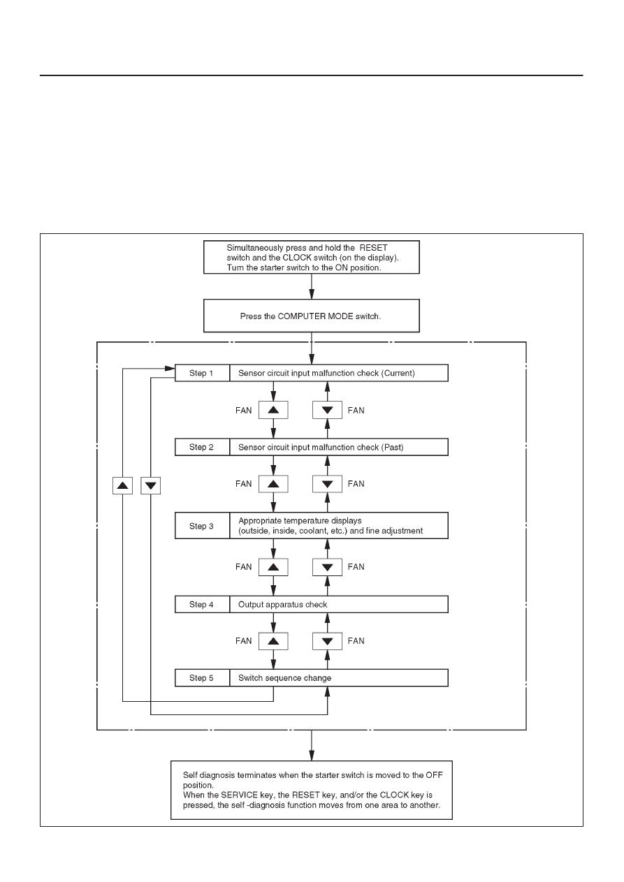
The Table below shows how to turn the self-diagnosis
function on and off.

Self-Diagnosis Operation Procedure

865R200033

1A–92 HEATING, VENTILATION AND AIR CONDITIONING (HVAC)

Step

Action

Value(s)

Yes

No

1

1. Allow the engine to idle until it completely warms up.
2. Turn the starter switch to the OFF position.
3. Place a 60–watt lamp approximately 15 cm from the

sun sensor.

NOTE: This procedure is best performed at night or in
a dark, unlit area.

Is the action complete?

—

Go to 

Step 2

—

2

Simultaneously press and hold the RESET key and the
CLOCK key (display unit).
Move the starter switch to start the engine.

Does DIAG appear on the display?

—

Go to 

Step 3

Replace

display unit

3

Press the COMPUTER MODE key.

Does DIAG AIRCON appear on the display?

—

Go to 

Step 4

Replace

audio unit

4

NOTE: A ’1’ should appear in the set temperature
segment of the display.

Does ’0’ appear in the outside air segment of the
display?

—

Go to 

Step 6

Go to 

Step 5

5

Repair or replace damaged parts.

NOTE: Refer to 

Step 1 Trouble Code Table.

Is the action complete?

—

Go to 

Step 1

—

6

Press and release the 


 fan switch (one time only).

NOTE: A ’2’ should appear in the set temperature
segment of the display.

Does ’0’ appear in the outside air segment of the
display?

—

Go to 

Step 8

Go to 

Step 7

7

Repair or replace damaged parts.

NOTE: Refer to 

Step 2 Trouble Code Table.

Is the action complete?

—

Go to 

Step 1

—

8

Press and release the 


 fan switch (one time only).

NOTE:

D

Refer to 

Step 3 Sensor Output Check for a sample

output value.

D

A ’3’ should appear in the set temperature
segment of the display.

Does the correct sensor output value appear in the
outside air segment of the display?

—

Go to 

Step 10

Go to 

Step 9

9

Repair or replace damaged parts.

NOTE: Refer to 

Trouble Spot Inspection.

Is the action complete?

—

Go to 

Step 1

—

10

Press and release the 


 fan switch one time only.

NOTE: Refer to 

Step 4 (Operation Check) for display

readings and inspection steps.

Are all parts operating normally?

—

Go to 

Step 12

Go to 

Step 11

HEATING, VENTILATION AND AIR CONDITIONING (HVAC) 1A–93

Step

No

Yes

Value(s)

Action

11

Repair or replace damaged parts.

NOTE: Refer to 

Trouble Spot Inspection.

Is the action complete?

—

Go to 

Step 1

—

12

1. Press and release the 


 fan switch (one time only).

2. Press the DEF switch several times.

NOTE: A ’3’ should appear in the set temperature
segment of the display.

Does the correct sequence pattern (1, 2, 1, 2) appear in
the outside air segment of the display?

—

Go to 

Step 15

Go to 

Step 13

13

Perform diagnosis for DEF switch, intake actuator, and
AUTO A/C control unit.

Have the diagnosis procedures been completed.

—

Go to 

Step 14

—

14

1. Press and release the 


 fan switch (one time only).

2. Press the DEF switch several times.

Are all parts operating normally?

—

Go to 

Step 15

Replace

display unit

15

Turn the starter switch OFF.

Is the action complete?

—

—

—

1A–94 HEATING, VENTILATION AND AIR CONDITIONING (HVAC)

STEP 1: Trouble Code Table

Trouble

Code

Defective Part

Trouble

Code

Defective Part

1

In Car Sensor Open Circuit

– 1

In Car Sensor Short Circuit

2

Ambient Sensor Open Circuit

– 2

Ambient Sensor Short Circuit

3

Sun Sensor Open Circuit

– 3

Sun Sensor Short Circuit

4

Duct Sensor Open Circuit

– 4

Duct Sensor Short Circuit

5

Mix Potentiometer Open Circuit

– 5

Mix Potentiometer Short Circuit

6

Mode Encoder Open Circuit

7

Intake Encoder Open Circuit

0

No Defective Part

STEP 2: Trouble Code Table

Trouble

Code

Defective Part

Trouble

Code

Defective Part

1

In Car Sensor Open Circuit

– 1

In Car Sensor Short Circuit

2

Ambient Sensor Open Circuit

– 2

Ambient Sensor Short Circuit

3

Not Used

– 3

Sun Sensor Short Circuit

4

Duct Sensor Open Circuit

– 4

Duct Sensor Short Circuit

5

Mix Potentiometer Open Circuit

– 5

Mix Potentiometer Short Circuit

6

Mode Encoder Open Circuit

7

Intake Encoder Open Circuit

0

No Defective Part


Content   ..  28  29  30  31   ..