Isuzu Trooper (1998-2002 year). Manual - part 779


  Index      Isuzu     Isuzu Trooper - service repair manual 1998-2002 year


Search            


Content   ..  777  778  779  780   ..


Isuzu Trooper (1998-2002 year). Manual - part 779


TRANSMISSION CONTROL SYSTEM (4L30–E)

7A1–25

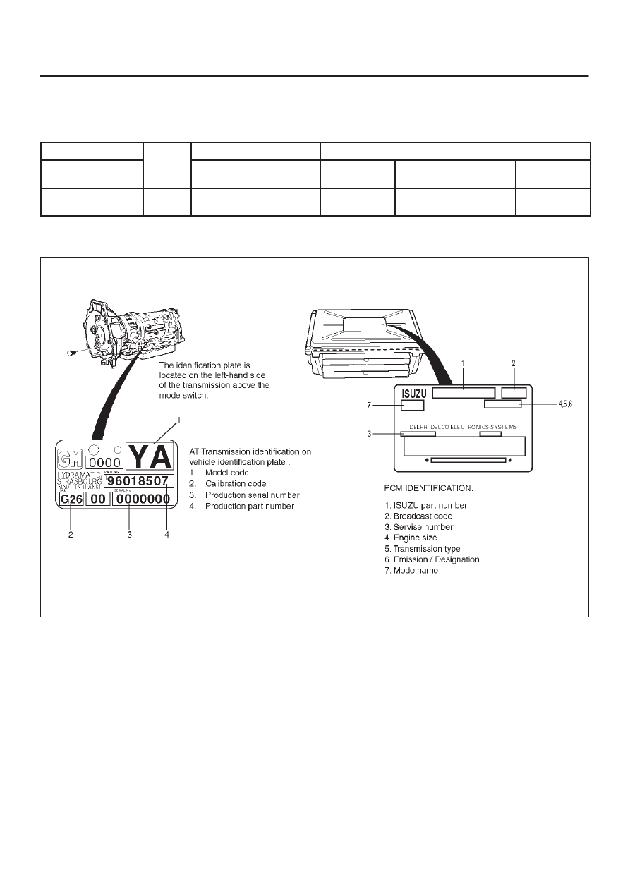
Transmission And PCM Identification

The chart below contains a list of all important information
concerning rear axle ratio, Powertrain Control Module
(PCM), and transmission identification.

VEHICLE

Rr axle

PCM

TRANSMISSION

Type

Engine

Rr axle

Ratio

ISUZU Parts No.

Calibration

Code

Isuzu Part No.

Model Code

Isuzu /

UBS

3.5L V6

4.100

8–97264–698–0
8–97264–700–2

G26

8–96018–507–0

YA

Isuzu UBS

240RY004

7A1–26 TRANSMISSION CONTROL SYSTEM (4L30–E)

Diagnostic Trouble Code (DTC)
Identification

DTC

NUMBER

DTC NAME

DTC TYPE

MIL “CHECK

ENGINE”

“CHECK

TRANS”

P0218

Transmission Fluid Over Temperature

D

P0705

Transmission Range Switch (Mode Switch) Illegal
Position

D

P0706

Transmission Range Switch (Mode Switch)
Performance

D

P0711

Transmission Fluid Temperature (TFT) Sensor
Performance

D

P0712

Transmission Fluid Temperature (TFT) Sensor
Circuit Low Input

D

P0713

Transmission Fluid Temperature (TFT) Sensor
Circuit High Input

D

P0719

Brake Switch Circuit Low (Stuck ON)

D

P0722

Automatic Transmission Output Speed Sensor
(OSS) Low Input

B

ON

Flash

P0723

Automatic Transmission Output Speed Sensor
(OSS) Intermittent

B

ON

Flash

P0724

Brake Switch Circuit High (Stuck OFF)

D

P0730

Gear Error Without Input Speed

C

Flash

P0742

Torque Converter Clutch (TCC) System Stuck ON

B

ON

Flash

P0748

Pressure Control Solenoid (PCS) (Force Motor)
Circuit Electrical

C

Flash

P0751

Shift Solenoid A Performance (Stuck OFF)

B

ON

Flash

P0752

Shift Solenoid A Performance (Stuck ON)

B

ON

Flash

P0753

Shift Solenoid A Electrical

B

ON

Flash

P0756

Shift Solenoid B Performance (Stuck OFF)

B

ON

Flash

P0757

Shift Solenoid B Performance (Stuck ON)

B

ON

Flash

P0758

Shift Solenoid B Electrical

B

ON

Flash

P1850

Brake Band Apply Solenoid Malfunction

D

P1860

TCC Solenoid Electrical

B

ON

Flash

P1870

Transmission Component Slipping (TCC Stuck
OFF)

B

ON

Flash

DTC TYPE

DEFINITION

B

Emission related, turn on MIL (Check Engine) and flashing Check Trans after 2 consecutive trips
(Removal to confirmed)

C

Non–emission related, flashing Check Trans on 1st failure

D

Non–emission related, no lamps

TRANSMISSION CONTROL SYSTEM (4L30–E)

7A1–27

DTC P0218 Transmission Fluid Over Temperature

LHD

D07R200043

RHD

D07R200044

Circuit Description

The Transmission Fluid Temperature (TFT) sensor is a
thermister that controls the signal voltage to the PCM.
The PCM supplies a 5–volt reference to the sensor on
circuit RED/WHT. When the transmission fluid is cold, the
sensor resistance is high and the PCM will sense high
signal voltage.  As the fluid temperature warms to a
normal transmission operating temperature of 100

°

C

(212

°

F), the sensor resistance becomes less and the

voltage decreases to 1.5 to 2.0 volts.
This DTC detects a high transmission temperature for a
long period of time.  This is a type “D” DTC.

Conditions For Setting The DTC

D

No TFT DTCs P0712 or P0713.

D

TFT is greater than 135

°

C (275

°

F).

D

All conditions met for 21 seconds.

Action Taken When The DTC Sets

D

Hot mode TCC Shift Pattern.

D

The PCM will not illuminate the Malfunction Indicator
Lamp (MIL).

D

ATF Lamp ON. (TFT is greater than 145

°

C (293

°

F).)

D

Disable E–side TCC OFF request.

Conditions For Clearing The DTC

D

The DTC can be cleared from the PCM history by
using a scan tool.  

D

The DTC will be cleared from history when the vehicle
has achieved 40 warm–up cycles without a failure
reported.

D

The PCM will cancel the DTC default actions when
the fault no longer exists and the ignition is cycled “off”
long enough to power down the PCM.

7A1–28 TRANSMISSION CONTROL SYSTEM (4L30–E)

Diagnostic Aids

D

Inspect the wiring for poor electrical connections at
the PCM and at the transmission 16–way connectors.
Look for possible bent, backed out, deformed, or
damaged terminals. Check for weak terminal tension
as well.

Also check for a chafed wire that could short to bare
metal or other wiring.  Inspect for a broken wire inside
the insulation.

D

When diagnosing for a possible intermittent short or
open condition, move the wiring harness while
observing test equipment for a change.

D

Check harness routing for a potential short to ground
in circuit RED/WHT.

D

Scan tool TFT sensor temperature should rise
steadily to about 100

°

C (212

°

F), then stabilize.

D

Check for a “skewed” (mis–scaled) sensor by
comparing the TFT sensor temperature to the
ambient temperature after a vehicle cold soak.  A
“skewed” sensor can cause delayed garage shifts or
TCC complaints.

D

Check for a possible torque converter stator problem.

D

Verify customer driving habits, trailer towing, etc.

Test Description

The numbers below refer to the step numbers on the
diagnostic chart.
3. This test checks for a “skewed” sensor or shorted

circuit.

4. This test simulates a TFT DTC P0713.

DTC P0218 Transmission Fluid Over Temperature 

Step

Action

Yes

No

1

Were you sent here from the “Powertrain On–Board Diagnostic
(OBD) System Check”?

Go to Step 2

Go to OBD

System Check

Refer to

Driveability and

Emissions in

Engine section

2

Perform the following checks:

D

Check for possible engine system problems.

D

Transmission fluid checking procedure.  Refer to Checking
Transmission Fluid Level and Condition in Automatic
Transmission (4L30–E) Section.

Were the checks performed?

Go to Step 3

3

1. Install the scan tool.
2. With the engine “off”, turn the ignition switch “on”.

NOTE: Before clearing DTC(s), use the scan tool to record “Failure
Records” for reference, as data will be lost when “Clear Info”
function is used.

3. Record the DTC “Failure Records”.

Is the TFT sensor signal voltage less than 1.54 volts?

Go to Step 4

Go to Diagnostic

Aids

4

1. Turn the ignition “off”.
2. Disconnect the transmission 16–way connector H–69

(additional DTCs may set).

Is the TFT sensor signal voltage greater than 4.92 volts?

Go to Internal

Wiring Harness

Check.

Go to Step 5

5

Inspect/repair circuit RED/WHT for a short to ground.

Was a problem found?

Go to Step 7

Go to Step 6

6

1. Inspect the PCM for poor connections.
2. Replace the PCM if no poor connections were found.

Is the replacement complete?

Go to Step 7

7

1. After the repair is complete, use the scan tool to select “DTC”,

then “Clear Info” function and ensure the following conditions
are met:
TFT is less than 125

°

C (257

°

F) for at least 10 seconds.

2. Review the scan tool “DTC Info”.

Has the last test failed or is the current DTC displayed?

Begin diagnosis

again 

Go to Step 1

Repair verified
Exit DTC table


Content   ..  777  778  779  780   ..