Isuzu Trooper (1998-2002 year). Manual - part 707


  Index      Isuzu     Isuzu Trooper - service repair manual 1998-2002 year


Search            


Content   ..  705  706  707  708   ..


Isuzu Trooper (1998-2002 year). Manual - part 707


AUTOMATIC TRANSMISSION (AW30-40LE)

7A–25

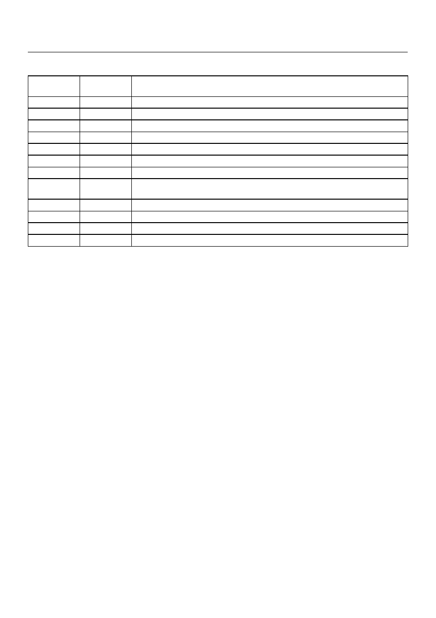
DIAGNOSTIC TROUBLE CODES (DTC) CHECK

DTC
NUMBER

FLASHING
CODE

DESCRIPTION

P0120

21

ANALOG THROTTLE SIGNAL FAILURE (VTH)

P0502

24

SPEED METER SENSOR FAILURE (SP1)

P0705

17

GEAR SELECTOR FAILURE (PRND2L)

P0710

16

OIL TEMPERATURE SENSOR FAILURE (OT2)

P0717

14

INPUT REVOLUTION SENSOR FAILURE (NC0)

P0722

11

OUTPUT REVOLUTION SENSOR FAILURE (SP2)

P0727

13

ENGINE REVOLUTION SIGNAL FAILURE (NE)

P0743

33

TORQUE CONVERTER CLUTCH CONTROL LOCK-UP (ON/OFF) SOLENOID
FAILURE (SL)

P0748

35

PRESSURE CONTROL SOLENOID FAILURE (STH)

P0753

31

SOLENOID 1 FAILURE (S1)

P0758

32

SOLENOID 2 FAILURE (S2)

P1121

23

ANALOG THROTTLE SIGNAL FAILURE (VREF, VGND)

7A–26

AUTOMATIC TRANSMISSION (AW30-40LE)

DTC P0120 (FLASHING CODE 21) ANALOG THROTTLE SIGNAL FAILURE (VTH)

D07RY00023

Circuit description:
When the signal of the engine throttle position sensor
located on the accelerator pedal is supplied to the TCM,
the TCM judges the opening condition of the throttle.
The shift point of the transmission is determined by this
opening condition of the throttle.

Fail-safe control:
The TCM controls fail-safe by detecting analog throttle
signal (VTH) failure.

Failure detection:

•When the throttle input voltage is detected less than

0.112V or more than 4.417V for 2.0 seconds.

Contents of control:
At failure detection

•Throttle opening for line pressure control ... Throttle

opening 100%

•Throttle opening for shift control ... Throttle opening

0%

•Lock-up control inhibit

•Up hill and down hill control inhibit

•Squat control inhibit

At failure decision

Executes following items in addition to above control
items at failure detection.

•Blinks "CHECK TRANS" lamp

•Stores the failure information in failure-memory

Conditions of turning "CHECK TRANS" lamp off: 
Turns “CHECK TRANS” lamp off when judged 0km/h by
output revolution sensor after throttle signal input voltage
is detected more than 0.112V and less than 4.717V.
(however, uses 0 km/h judgment by back-up vehicle
speed at output revolution failure)

Reversion conditions from fail-safe:
At failure detection

Immediately recovers when the throttle input voltage
is detected more than 0.112V and less than 4.717V.

At failure decision

Recovers at the same time as the conditions of
turning “CHECK TRANS” lamp off are satisfied.

Test description:

The following numbers correspond to circled numbers on
the diagnostic chart.

(1) Check that the throttle input voltage is 0.25 to 0.45V.

(2) At this test, check that as the throttle opens, the

voltage goes up and that the voltage reaches 3.74 to
4.56V at the full open status.

(3) Check the power supply voltage (4.75 – 5.25V) of the

throttle position sensor.

Diagnostic aids:
An intermittent may be caused by a poor connection,
rubbed through wire insulation or a wire broken inside
the insulation. Inspect related harness connector for
backed out terminals, improper mating, broken locks,
improperly formed or damaged terminals, poor terminal
to wire connection and damaged harness.

AUTOMATIC TRANSMISSION (AW30-40LE)

7A–27

DTC P0120 (FLASHING CODE 21) ANALOG THROTTLE SIGNAL FAILURE (VTH)

DTCP0120

7A–28

AUTOMATIC TRANSMISSION (AW30-40LE)

DTC P0502 (FLASHING CODE 24) SPEED METER SENSOR FAILURE (SP1)

D07RY00024

Circuit description:
Speed information is provided by the speed meter sensor
to the meter.
In the meter, the pulses of the speed meter sensor are
converted to speed signals (pulses), and these signals
are output to the TCM. The TCM converts these pulse
voltages to km/h signals.

Fail-safe control:
The TCM controls fail-safe by detecting speed meter
signal failure.

Failure detection:

• When not even 1 pulse is input in the speed meter

signal during the time 100 pulses are input in the
output revolution sensor signal.

• When not even 1 pulse is input in the speed meter

signal during the time 27 pulses are input in the
output revolution sensor signal.

Contents of control:
At failure detection

•Keeps the condition of transfer (High/Low judgment)

just before detection until vehicle speed is 0km/h,
and changes shift map to L4 map (3

4 UP None) at

vehicle speed is 0km/h.

• Uses high oil temperature map according to shift

map priority at correct oil temperature control.

• Up hill and down hill control inhibit.

• Stores the failure information in failure -memory.

• The failure detection of oil temperature sensor inhibit

At failure decision

Executes following items in adition to above control
items at failure detection.

•Blinks "CHECK TRANS" lamp

Conditions of turning "CHECK TRANS" lamp off: 
Turns "CHECK TRANS" lamp off when judged 0km/h by
speed meter sensor after more than 1 pulse are input in
the speed meter signal during the time 27 pulses are

input in the output revolution sensor.

Reversion conditions from fail-safe:
At failure detection and decision
Recovers at the same time as the conditions of turning
“CHECK TRANS” lamp off are satisfied.

Test description:

The following numbers correspond to circled numbers on
the diagnostic chart.

(1) The cause of DTC P0502 setting is due to the

operation fault of the speed meter.

(2) Speed signals are output from the meter. The sensor

power supply is given from the TCM.

Diagnostic aids:
An intermittent may be caused by a poor connection,
rubbed through wire insulation or a wire broken inside
the insulation. Inspect related harness connector for
backed out terminals, improper mating, broken locks,
improperly formed or damaged terminals, poor terminal
to wire connection and damaged harness.


Content   ..  705  706  707  708   ..