Isuzu Trooper (1998-2002 year). Manual - part 696
7A–76
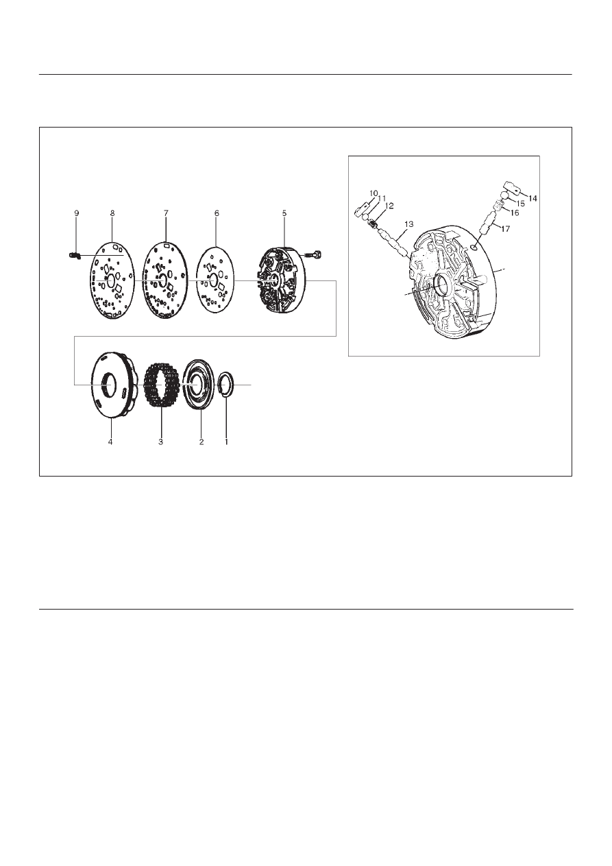
AUTOMATIC TRANSMISSION (4L30–E)
Reverse Clutch Piston And Center Support
Disassembled View
242RY001
Legend
(1) Retaining Ring
(2) Spring Seat
(3) Springs
(4) Piston Assembly
(5) Center Support
(6) Gasket
(7) Transfer Plate
(8) Gasket
(9) Restrictor
(10) Retainer Plate
(11) Plug
(12) Spring
(13) Overrun Lock Out Valve
(14) Retainer Plate
(15) Plug
(16) Spring
(17) Reverse Lock Out Control Valve