Isuzu Trooper (1998-2002 year). Manual - part 631


  Index      Isuzu     Isuzu Trooper - service repair manual 1998-2002 year


Search            


Content   ..  629  630  631  632   ..


Isuzu Trooper (1998-2002 year). Manual - part 631


6E–172

4JX1–TC ENGINE DRIVEABILITY AND EMISSIONS

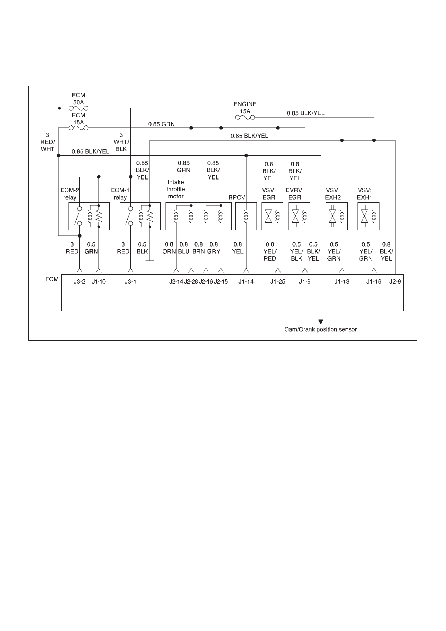
Diagnostic Trouble Code (DTC) P1657 (Flash DTC 76) 

ECM Main Relay Circuit Open/Short

060RW135

Circuit Description

The ECM main relay circuit receives current through ECM
50A fuse from the battery, current flowing in the order of
the ECM main relay and ECM.

Action Taken When the DTC Sets

D

The ECM will illuminate the malfunction indicator lamp
(MIL) the first time the fault is detected.

D

The ECM will store conditions which were present
when the DTC was set as Freeze Frame and in the
Failure Records data.

Conditions for Clearing the MIL/DTC

D

DTC P1657 can be cleared by using the Tech 2 “Clear
Info” function or by disconnecting the ECM battery
feed.

Diagnostic Aids

Check for the following conditions:

D

Poor connection at ECM – Inspect harness connectors
for backed-out terminals, improper mating, broken
locks, improperly formed or damaged terminals, and
poor terminal-to-wire connection.

D

Damaged harness – Inspect the wiring harness for
damage.

6E–173

4JX1–TC ENGINE DRIVEABILITY AND EMISSIONS

DTC P1657 – ECM Main Relay Circuit Open/Short


Step

Action

Value(s)

Yes

No

1

Was the “On-Board Diagnostic (OBD) System Check”
performed?

Go to 

Step 2

Go to 

OBD

System

Check

2

1. Check the Fuse 50A·ECM and 15A·Eng.
2. If the Fuse is open, replace it as necessary.

Was the Fuse open?

Verify repair

Go to 

Step 3

3

1. Ignition “ON,” engine “OFF.”
2. Review and record Tech 2 Failure Records data.
3. Operate the vehicle within Failure Records

conditions as noted.

4. Using a Tech 2, monitor the “DTC” info for DTC

P1657.

Does the Tech 2 indicate DTC P1657 failed?

Go to 

Step 4

Refer to

Diagnostic

Aids

4

Check the ECM Main Relay circuit between the Fuse
and the ECM Main Relay for a poor connection and
repair the terminal if necessary.

Did the terminal require repair?

Verify repair

Go to 

Step 5

5

Check the ECM Main Relay for a damage and Replace
the ECM (Refer to the Data Programming in Case of
ECM change) Main Relay if necessary.

Did the ECM Main Relay require replacement?

Verify repair

Go to 

Step 6

6

Check the ECM Main Relay circuit for a poor
connection at the ECM and replace the terminal if
necessary.

Did the terminal require replacement?

Verify repair

Go to 

Step 7

7

Check the ECM Main Relay Ground circuit for a poor
connection and repair the terminal if necessary.

Did the terminal require repair?

Verify repair

Go to 

Step 8

8

Check the ECM Main Relay power circuit for a poor
connection and repair the terminal if necessary.

Did the terminal require repair?

Verify repair

Go to 

Step 9

9

Replace the ECM (Refer to the Data Programming in
Case of ECM change) Main Relay.

Is the action complete?

Verify repair

Go to 

Step 10

10

Replace the ECM (Refer to the Data Programming in
Case of ECM change).

Is the action complete?

Verify repair

6E–174

4JX1–TC ENGINE DRIVEABILITY AND EMISSIONS

Diagnostic Trouble Code (DTC) P1589 (Flash DTC 47) 

Transmission SW Circuit Open/Short

060RW131

Circuit Description

The trans mission SW circuit receives current through
ELEC IG 10A fuse from the battery, current flowing in the
order of the trans mission SW and ECM.

Action Taken When the DTC Sets

D

The ECM will illuminate the malfunction indicator lamp
(MIL) the first time the fault is detected.

D

The ECM will store conditions which were present
when the DTC was set as Freeze Frame and in the
Failure Records data.

Conditions for Clearing the MIL/DTC

D

DTC P1589 can be cleared by using the Tech 2 “Clear
Info” function or by disconnecting the ECM battery
feed.

Diagnostic Aids

Check for the following conditions:

D

Poor connection at ECM – Inspect harness connectors
for backed-out terminals, improper mating, broken
locks, improperly formed or damaged terminals, and
poor terminal-to-wire connection.

D

Damaged harness – Inspect the wiring harness for
damage.  If the harness appears to be OK, observe the
throttle position display on the Tech 2 while moving
connectors and wiring harnesses related to the TP
sensor.  A change in the display will indicate the
location of the fault.

If DTC P1589 cannot be duplicated, the information
included in the Failure Records data can be useful in
determining vehicle mileage since the DTC was last set.

DTC P1589 – Transmission Circuit Open/Short


Step

Action

Value(s)

Yes

No

1

Was the “On-Board Diagnostic (OBD) System Check”
performed?

Go to 

Step 2

Go to 

OBD

System

Check

2

Check the Fuse 10A for a open circuit and replace the
Fuse if necessary.

Did the Fuse require replacement?

Verify repair

Go to 

Step 3

6E–175

4JX1–TC ENGINE DRIVEABILITY AND EMISSIONS

DTC P1589 – Transmission Circuit Open/Short

  (Cont'd)

Step

No

Yes

Value(s)

Action

3

1. Ignition “ON,” engine “OFF.”
2. Review and record Tech 2 Failure Records data.
3. Operate the vehicle within Failure Records

conditions as noted.

4. Using a Tech 2, monitor the “DTC” info for DTC

P1589.

Does the Tech 2 indicate DTC P1589 failed?

Go to

Step 4

(A/T)

Go to

Step 6

(M/T)

Refer to

Diagnostic

Aids

4

Check the Indicator Lamp correct indicated for a
correct indication on the Meter. (A/T only)

Did the Indicator Lamp correct indicated?

Go to 

Step 5

Go to 

Step 8

5

Check the Trans Mission SW signal circuit for a poor
connection at the ECM and replace the terminal if
necessary.

Did the terminal require replacement?

Verify repair

Go to 

Step 8

6

Check the Trans Mission SW circuit for a poor
connection at the Trans Mission SW and replace the
terminal if necessary.

Did the terminal require replacement?

Verify repair

Go to 

Step 7

7

Replace the Trans Mission SW.

Is the action complete?

Verify repair

Go to 

Step 8

8

Replace the ECM (Refer to the Data Programming in
Case of ECM change).

Is the action complete?

Verify repair


Content   ..  629  630  631  632   ..