Isuzu Trooper (1998-2002 year). Manual - part 621
6E–132
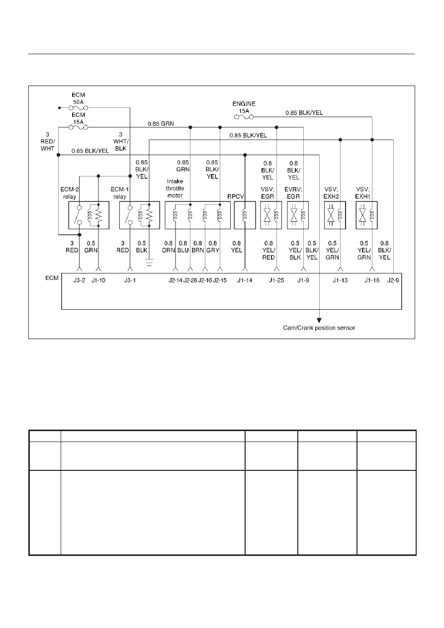
4JX1–TC ENGINE DRIVEABILITY AND EMISSIONS
Diagnostic Trouble Code (DTC) P1404 (Flash DTC 31)
EGR VSV Circuit
060RW135
Circuit Description
The Engine control module (ECM) monitors the EGR
valve input to ensure that the valve responds properly to
commands from the ECM, and to detect a fault if VSV is
stuck open. When the VSV is fixing at closed and opening
the ECM will set DTC P1404.
Diagnostic Aids
Check for the following conditions:
D
Poor connection or damaged VSV–inspect the wiring
harness for damage.
DTC P1404 – EGR VSV Circuit
Step
Action
Value(s)
Yes
No
1
Was the “On-Board Diagnostic (OBD) System Check”
performed?
—
Go to
Step 2
Go to
OBD
System
Check
2
1. Ignition “ON”, engine “OFF”, review and record
scan tool Failure Records data.
2. Operate the vehicle within Failure Records
conditions as noted.
3. Using a scan tool, monitor “Specific DTC” info for
DTC P1404 until the DTC P1404 test runs. Note the
result.
Does the scan tool indicates DTC P1404 failed this
ignition?
—
Go to
Step 3
Refer to
Diagnostic
Aids