Isuzu Trooper (1998-2002 year). Manual - part 556


  Index      Isuzu     Isuzu Trooper - service repair manual 1998-2002 year


Search            


Content   ..  554  555  556  557   ..


Isuzu Trooper (1998-2002 year). Manual - part 556


6A – 32 ENGINE MECHANICAL
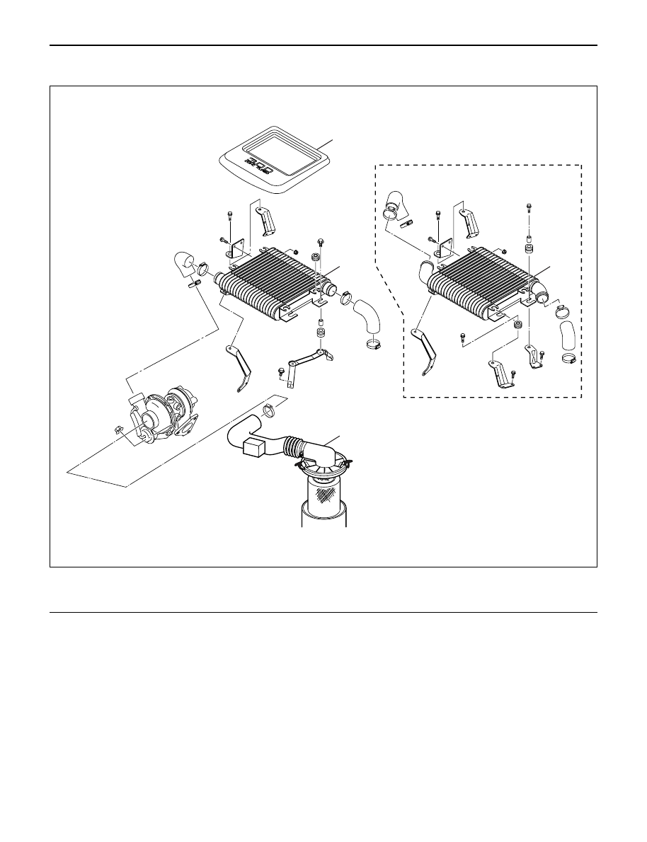
INTERCOOLER

REMOVAL

1. Disconnect the battery ground cable.
2. Remove air cleaner cover and air duct.
3. Remove intercooler cover.
4. Remove intercooler assembly.

1) Remove rubber hose from between intercooler

outlet and intake manifold inlet.

2) Remove rubber hose from between

turbocharger outlet and intercooler inlet.

3) Remove intercooler assembly fixing bolts from

the bracket, remove intercooler assembly.

INSTALLATION

1. Intercooler assembly

1) Connect outlet hose to intake manifold.

Torque : 4 N·m (0.4 kg·m/35 lb in)

2) Connect inlet hose from turbocharger to

intercooler.

Torque : 4 N·m (0.4 kg·m/35 lb in)

3) Install intercooler and tighten fixing bolts to the

specified torque.

Torque : 20 N·m (2.0 kg·m/14 lb ft)

2. Install intercooler cover.
3. Install air cleaner cover and air duct.
4. Connect the battery ground cable.

For Europe

2

3

3

1

135R200003

Legend

(1)

Air Cleaner Cover & Air Duct

(2)

Intercooler Cover

(3)

Intercooler Assembly

ENGINE MECHANICAL 6A – 33

CYLINDER HEAD COVER

REMOVAL

1. Disconnect battery ground cable.
2. Remove clip, remove air cleaner cover and air duct.
3. Remove intercooler assembly.

Refer to “Intercooler” in this manual.

4. Remove PCV hose.
5. Remove bolts which fix noise insulator cover then

remove noise insulator cover and insulator.

6. Remove high pressure oil pipe at cylinder head

side.
Take care when removing the injector oil pipe,
because sometimes, during removal, your hand
can be injured by the remaining high pressure oil.

INSTALLATION

1. Cylinder head cover.

1) Install the cylinder head cover gasket to cylinder

head cover.

2) The gasket must be set perfectly with no loose

areas.

3) Apply liquid gasket (TB1207B or equivalent) to

the rubber seal of the camshaft end, injector
harness gasket area and No. 1 camshaft
bracket.

4) Tighten cylinder head cover fixing bolts to the

specified torque.

Torque : 9 N·m (0.9 kg·m/78 lb in)

2. Fill with about 300 cc of engine oil from the high

pressure oil pipe installation port of the oil rail using
an oil rail filler. If assembled without filling the oil rail
with oil, the time for starting the engine will be
longer.

3. Install the high pressure oil pipe immediately and

tighten the sleeve nut to the specified torque.

Torque : 78 N·m (8.0 kg·m/58 lb ft)

1

7

2

3

4

5

6

010R200006

Legend

(1)

Noise Insulator Cover

(2)

Insulator

(3)

Bolt

(4)

Oil Seal

(5)

Gasket

(6)

Cylinder Head Cover

(7)

Bolt

3~5

2~3

2~3

3~5

3~5

1~2

012RW119

6A – 34 ENGINE MECHANICAL

NOTE: Do not scratch the oil seal on the cylinder head
during installation of the high pressure oil pipe.

4. Install the noise insulator and its cover on the

cylinder head cover.

NOTE: Do not catch the injector harness with the noise
insulator cover.

5. Connect the PCV hose.
6. Install the intercooler assembly.

Refer to “Intercooler” in this manual.

7. Install air cleaner cover and air duct.
8. Connect battery ground cable.

ENGINE MECHANICAL 6A – 35

INTAKE MANIFOLD

REMOVAL

1. Drain engine coolant and disconnect water hose

from thermostat hosing.

2. Remove intercooler assembly

Refer to “Intercooler” in this manual.

3. Remove bracket bolt of oil level gauge guide tube.
4. Remove PCV Hose.
5. Remove hoses from EGR, EGR vacuum sensor

and inlet/outlet of heater.

6. Disconnect harness connector form MAP sensor,

EGR vacuum sensor, ETC sensor, water
temperature unit, IAT sensor and EVRV.

7. Remove high pressure oil pipe.
8. Remove the two way valve.
9. Remove fuel pipe from between intake manifold

and high pressure oil pump.

10. Remove fixing bolts and nuts on the intake

manifold, then remove the intake manifold
assembly.

INSTALLATION

1. Install the intake manifold, tighten bolts and nuts to

the specified torque.

Torque : 20 N·m (2.0 kg·m/14 lb ft) for bolt and nut

2. Install the fuel pipe and tighten to the specified

torque.

Torque :

M16 bolt (apply engine oil) 4 N·m (0.4 kg·m/35
lb in)
Cap nut (M10) 13N·m (1.3 kg·m/113 lb in)
Fuel pipe (M10 apply engine oil) 14 N·m (1.4
kg·m/122 lb in)

3. Install two way valve.

Torque : 20 N·m (2.0 kg·m/14 lb ft)

4. Fill with about 300 cc of engine oil from the high

pressure oil pipe installation port of the oil rail using
an oil filler. If assembled without filling the oil rail
with oil, the time for starting the engine will be
longer.

5. Install the high pressure oil pipe immediately and

tighten the sleeve nut to the specified torque.

Torque : 78 N·m (8.0 kg·m/58 lb ft)

6. Reconnect harness connector to MAP sensor, EGR

vacuum sensor, ETC sensor, Water temperature
unit, IAT sensor and EVRV.

7. Connect the hoses to EGR valve, EGR vacuum

sensor, and water inlet/outlet pipe for heater.

8. Connect PCV hose.
9. Install the oil level gauge guide tube and tighten

bracket bolt.

10. Install the intercooler assembly.

Refer to “Intercooler” in this manual.

11. Connect the hose to the thermostat housing and fill

with engine coolant.

For Europe

2

1

3

3

1

4

2

025R200005

Legend

(1)

Intake Manifold

(2)

Throttle Valve Assembly

(3)

EGR Valve

(4)

Gasket


Content   ..  554  555  556  557   ..