Isuzu Trooper (1998-2002 year). Manual - part 482
6E–298
6VE1 3.5 ENGINE DRIVEABILITY AND EMISSIONS
Diagnostic Trouble Code (DTC)
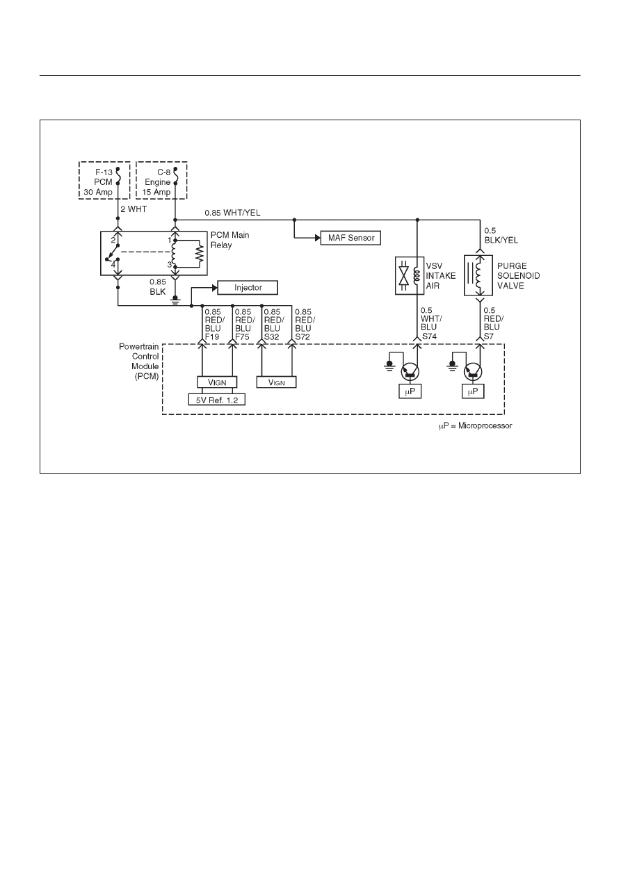
P0445 EVAP Purge Control Circuit Short
D06R200089
Circuit Description
The canister purge solenoid valve is controlled by the
Power Train Control Module (PCM). The PCM monitors
vacuum level via the fuel tank pressure sensor input.
At an appropriate time, the EVAP canister purge solenoid
is “ON,” allowing engine vacuum to draw a small vacuum
on the entire evaporative emissions system.
Conditions for setting the DTC
D
The Ignition is “ON”.
D
Engine is running.
D
System voltage is between 11.5 volts and 16 volts.
Action Taken When the DTC Sets
D
The PCM will ON the MIL after second trip with
detected the fault.
D
The PCM will store conditions which were present
when the DTC set as Freeze Frame and in the Failure
Records data.
Conditions for Clearing the MIL/DTC
D
The PCM will turn the MIL “OFF” on the third
consecutive trip cycle during which the diagnostic has
been run and the fault condition is no longer present.
D
A history DTC P0445 will clear after 40 consecutive trip
cycles during which the warm up cycles have occurred
without a fault.
D
DTC P0445 can be cleared using the Tech 2 “Clear
Info” function or by disconnecting the PCM battery
feed.
Diagnostic Aids
An intermittent may be caused by the following:
D
Poor connections.
D
Misrouted harness.
D
Rubbed through wire insulation.
D
Broken wire inside the insulation.
Check for the following conditions:
D
Poor connection at PCM-Inspect harness connectors
for backed out terminals, improper mating, broken
locks, improperly formed or damaged terminals, and
poor terminal to wire connection.
D
Damaged harness-Inspect the wiring harness for
damage. If the harness appears to be OK, observe the
EVAP purge solenoid display on the Tech 2 while
moving connectors and wiring harnesses related to the
sensor.
A change in the display will indicate the location of
the fault. If DTC P0445 cannot be duplicated, the
information included in the Failure Records data can
be useful in determined vehicle mileage since the
DTC was last set.
If it is determined that the DTC occurs intermittently,
performing the DTC P0445 Diagnostic Chart may
isolate the cause of the fault.