Isuzu Trooper (1998-2002 year). Manual - part 476
6E–274
6VE1 3.5 ENGINE DRIVEABILITY AND EMISSIONS
Diagnostic Trouble Code (DTC) P0356 Ignition 6 Control Circuit
D06R200098
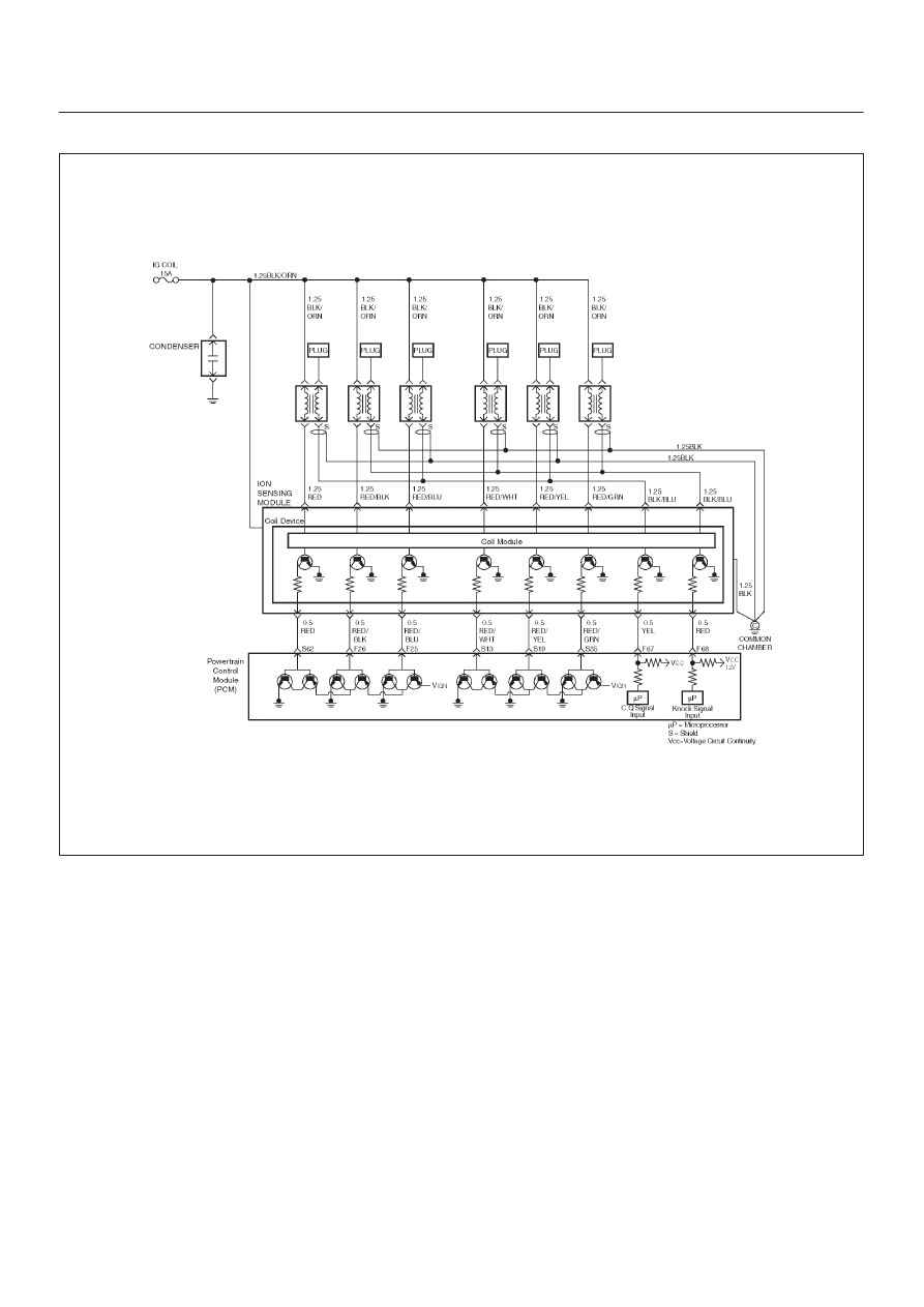
Circuit Description
ION Sensing Module has the function to energize and
de-energize the primary ignition coil in response to
signals from the PCM. The PCM controls ignition timing
and dwell time.
This diagnosis detects open circuit or short-circuiting in
the Ignition Electronic Spark Timing (EST) line by
monitoring EST signals. A failure determination is made
when the signal voltage remains higher or lower than the
threshold for corresponding fault code beyond a
predetermined time period.
When the PCM detects a problem on EST control circuit
6, it will set a DTC P0356.
Conditions for Setting the DTC
D
The ignition is “ON”.
D
The engine is running, determined by the 58X
crankshaft position input signal.
D
The output voltage is not equal to 5 volts when output
is “ON”.
D
The output voltage is not equal to 0 volts when output
is “OFF”.
D
Ten test failures occur within 10 samples of continuous
circuit monitoring.
Action Taken When the DTC Sets
D
The PCM will illuminate the malfunction indicator lamp
(MIL) the first time the fault is detected.
D
The PCM will store conditions which were present
when the DTC was set as Freeze Frame and in the
Failure Records data.
Conditions for Clearing the MIL/DTC
D
The PCM will turn the MIL “OFF” on the third
consecutive trip cycle in which the diagnostic has been
run and the fault condition is no longer present.
D
A history DTC P0356 will clear after 40 consecutive
warm-up cycles occur without a fault.
D
DTC P0356 can be cleared by using the Tech 2 “Clear
Info” function or by disconnecting the PCM battery
feed.