Isuzu Trooper (1998-2002 year). Manual - part 455


  Index      Isuzu     Isuzu Trooper - service repair manual 1998-2002 year


Search            


Content   ..  453  454  455  456   ..


Isuzu Trooper (1998-2002 year). Manual - part 455


6E–190

6VE1 3.5 ENGINE DRIVEABILITY AND EMISSIONS

Diagnostic Trouble Code (DTC) 

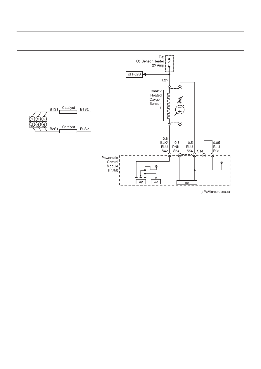
P0153 HO2S Slow Response Bank 2 Sensor 1

D06RY00175

Circuit Description

The powertrain control module (PCM) continuously
monitors the heated oxygen sensor (HO2S) activity for 90
seconds after “closed loop” has been enabled.  During the
monitoring period the PCM counts the number of times
that a rich-to-lean and lean-to-rich response is indicated
and adds the amount of time it took to complete all
rich-to-lean transitions and lean-to-rich transitions.  With
this information, an average time for  rich-to-lean and
lean-to-rich transitions can be determined.  If the average
response time of either transition is too slow, a DTC
P0153 will be set.
A lean-to-rich transition is indicated when the HO2S
voltage changes from less than 300 mV to greater than
600 mV.  A rich-to-lean transition is indicated when the
HO2S voltage changes from more than 600 mV to less
than 300 mV.  An HO2S that responds too slowly is likely
to be faulty and should be replaced.

Conditions for Setting the DTC

D

No related DTCs.

D

Engine coolant temperature (ECT) is above 60

°

C

(140

°

F).

D

The engine is operating in “closed loop”.

D

Engine has been running for over 60 seconds.

D

Canister purge duty cycle is above 2%.

D

Engine speed is between 1500 RPM and 3000 RPM.

D

Mass air flow is between 18 g/second and 42 g/second.

D

All above conditions are met for 3 seconds.

D

90 seconds after “closed loop” has been enabled, Bank
2 HO2S 1 average transition time between 300 mV
and 600 mV is too slow.  The lean-to-rich average
transition response time was longer than 94
milliseconds or the rich-to-lean average transition
response time was longer than 105 milliseconds.

Action Taken When the DTC Sets

D

The PCM will illuminate the malfunction indicator lamp
(MIL) after the second consecutive trip in which the
fault is detected.

D

The PCM will store conditions which were present
when the DTC set as Freeze Frame and in the Failure
Records data.

D

“Open loop” fuel control will be in effect.

Conditions for Clearing the MIL/DTC

D

The PCM will turn the MIL “OFF” on the third
consecutive trip cycle during which the diagnostic has
been run and the fault condition is no longer present.

D

A history DTC P0153 will clear after 40 consecutive
warm-up cycles have occurred without a fault.

D

DTC P0153 can be cleared by using the Tech 2 “Clear
Info” function or by disconnecting the PCM battery
feed.

6E–191

6VE1 3.5L ENGINE DRIVEABILITY AND EMISSIONS

Diagnostic Aids

Check for the following conditions:

D

Poor connection at PCM – Inspect harness connectors
for backed-out terminals, improper mating, broken
locks, improperly formed or damaged terminals, and
poor terminal-to-wire connection.

D

Damaged harness – Inspect the wiring harness for
damage.  If the harness appears to be OK, observe the
Bank 2 HO2S 1 display on the Tech 2 while moving
connectors and wiring harnesses related to the sensor.
A change in the display will indicate the location of the
fault.

Reviewing the Failure Records vehicle mileage since the
diagnostic test last failed may help determine how often
the condition that caused the DTC to be set occurs.  This
may assist in diagnosing the condition.

Test Description

Number(s) below refer to the step number(s) on the
Diagnostic Chart.
2. Verifies that the fault is currently present.

3. HO2S transition time, ratio mean volts and switching

DTCs set for multiple sensors indicate probable
contamination.  Before replacing the sensors,
isolate and correct the source of the contamination
to avoid damaging the replacement sensors.

6E–192

6VE1 3.5 ENGINE DRIVEABILITY AND EMISSIONS

DTC P0153 – HO2S Slow Response Bank 2 Sensor 1


Step

Action

Value(s)

Yes

No

1

Was the “On-Board Diagnostic (OBD) System Check”
performed?

Go to 

Step 2

Go to 

OBD

System

Check

2

NOTE: If any DTCs are set, (except P0133, P1133,
P1134, P1153, and/or P1154), refer to those DTCs
before proceeding with this diagnostic chart.

1. Install the Tech 2.
2. Idle the engine at operating temperature.
3. Operate the vehicle within parameters specified

under “Conditions for Setting the DTC” criteria
included in Diagnostic Support.

4. Using a Tech 2, monitor “DTC” info for DTC P0153

until the DTC P0153 test runs.

5. Note the test result.

Does the Tech 2 indicate DTC P0153 failed this
ignition?

Go to 

Step 3

Check the

Procedure

Refer to

Diagnostic

Aids

3

Did the Tech 2 also indicate DTC P0153, P1133,
P1134, P1153, and/or P1154 test failed this ignition?

Go to 

Step 17

Go to 

Step 4

4

Check for leaks at the pipe joints.

Are the joints leaking?

Go to 

Step 5

Go to 

Step 6

5

Tighten the U-bolt nuts at the leaking joint.

Is your action complete?

Go to 

Step 2

6

Check for gaskets that are damage or improperly
installed.

Are there damaged or misaligned gaskets?

Go to 

Step 7

Go to 

Step 8

7

1. Replace the damaged gaskets.
2. Align the connections.
3. Tighten the connections.

Is your action complete?

Go to 

Step 2

8

Check for loose exhaust flange connections.

Are the flange connections loose?

Go to 

Step 9

Go to 

Step 10

9

Tighten the stud nuts or bolts to specifications.

Is your action complete?

Go to 

Step 2

10

Check for burned or corroded exhaust pipes.

Are the exhaust pipes burned or corroded?

Go to 

Step 11

Go to 

Step 12

11

Replace the exhaust pipes, as required.

Is your action complete?

Go to 

Step 2

12

Check for leaks at the exhaust manifold.

Are there leaks at the exhaust manifold?

Go to 

Step 13

Go to 

Step 14

13

Tighten the bolts to specifications or replace the
manifold if necessary.

Is your action complete?

Go to 

Step 2

6E–193

6VE1 3.5L ENGINE DRIVEABILITY AND EMISSIONS

DTC P0153 – HO2S Slow Response Bank 2 Sensor 1

  (Cont'd)

Step

No

Yes

Value(s)

Action

14

1. Visually/physically inspect the following items:

D

Ensure that the Bank 2 HO2S 1 is securely
installed.

D

Check for corrosion on terminals.

D

Check terminal tension (at Bank 2 HO2S 1 and
at the PCM).

D

Check for damaged wiring.

Was a problem found in any of the above areas?

Go to 

Step 18

Go to 

Step 15

15

1. Disconnect Bank 2 HO2S 1.
2. Ignition “ON”.
3. Using a DVM at the PCM side of the HO2S 1

connector, measure the voltage between the high
signal circuit and ground. 

Are both voltages in the specified range?

3-4 V

Go to 

Step 16

Go to 

Step 19

16

1. With Bank 2 HO2S 1 disconnected, jumper the high

and low (PCM side) signal circuits to ground.

2. Ignition “ON”.
3. Using a Tech 2, monitor the Bank 2 HO2S 1 voltage.

Does the Tech 2 indicate less than 10 mV and
immediately return to about 450 mV when the jumper is
removed?

Go to 

Step 21

Go to 

Step 22

17

Replace the affected heated oxygen sensors.

NOTE: Before replacing the sensors, the cause of the
contamination must be determined and corrected.

D

Fuel contamination.

D

Use of improper RV sealant.

D

Engine oil/coolant consumption.

Is the action complete?

Verify repair

18

Repair condition as necessary.

Is the action complete?

Verify repair

19

Check for faulty PCM connections or terminal damage.

Is the action complete?

Verify repair

Go to 

Step 20

20

Repair open, short or grounded signal circuit.

Is the action complete?

Verify repair

21

Replace Bank 2 HO2S 1.

Is the action complete?

Verify repair

22

Replace the PCM.

IMPORTANT: The replacement PCM must be
programmed.  Refer to 

On-Vehicle Service in

Powertrain Control Module and Sensors for
procedures.

And also refer to latest Service Bulletin.

Check to see if the Latest software is released or not.
And then Down Load the LATEST PROGRAMMED
SOFTWARE to the replacement PCM.

Is the action complete?

Verify repair


Content   ..  453  454  455  456   ..