Isuzu Trooper (1998-2002 year). Manual - part 452


  Index      Isuzu     Isuzu Trooper - service repair manual 1998-2002 year


Search            


Content   ..  450  451  452  453   ..


Isuzu Trooper (1998-2002 year). Manual - part 452


6E–178

6VE1 3.5 ENGINE DRIVEABILITY AND EMISSIONS

Diagnostic Trouble Code(DTC) 

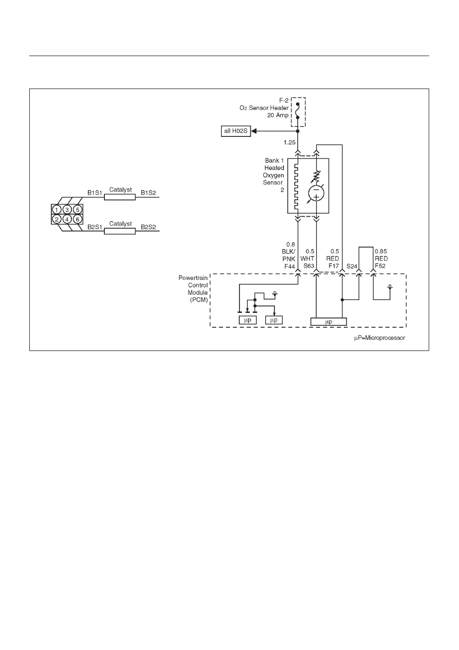
P0140 HO2S Circuit Insufficient Activity Bank 1 Sensor 2

D06RY00173

Circuit Description

To control emissions of hydrocarbons (HC), carbon
monoxide (CO), and oxides of nitrogen (NOx), a
three-way catalytic converter is used.  The catalyst within
the converter promotes a chemical reaction which
oxidizes the HC and CO present in the exhaust gas,
converting them into harmless water vapor and carbon
dioxide.  The catalyst also reduces NOx, converting it to
nitrogen.  The powertrain control module (PCM) has the
ability to monitor this process using the Bank 1 HO2S 1
and the Bank 1 HO2S 2 heated oxygen sensors.  The
Bank 1 HO2S 2 sensor produces an output signal which
indicates the amount of oxygen present in the exhaust
gas entering the three-way catalytic converter.  The Bank
1 HO2S 2 sensor produces an output signal which
indicates the oxygen storage capacity of the catalyst; this
in turn indicates the catalyst’s ability to convert exhaust
gases efficiently.  If catalyst is operating efficiently, the
Bank 1 HO2S 1 signal will be far more active than that
produced by the Bank 1 HO2S 2 sensor.  If the Bank 1
HO2S 2 signal voltage remains between 400 mV and
500 mV for an extended period of time, DTC P0140 will be
set. Heated oxygen sensors are used to minimize the
amount of time required for “closed loop” fuel control
operation and to allow accurate catalyst monitoring.  The
oxygen sensor heater greatly decreases the amount of
time required for fuel control sensors Bank 1 HO2S 1 and
Bank 2 HO2S 1 to become active.  Oxygen sensor
heaters are required by post-catalyst monitor sensors to

maintain a sufficiently high temperature for accurate
exhaust oxygen content readings further from the engine.

Conditions for Setting the DTC

D

No related DTCs.

D

Engine coolant temperature is above 60

°

C (140

°

F).

D

The engine has been running for over 5 seconds.

D

Oxygen sensor heater is functioning properly.

D

Engine is operating in “closed loop”

D

Bank 1 HO2S 2 signal voltage remains between
426 mV and 474 mV for a total of 106 seconds over a
125-second period of time.

Action Taken When the DTC Sets

D

The PCM will ON the MIL after second trip with
detected fault.

D

The PCM will store conditions which were present
when the DTC was set as Freeze Frame and in the
Failure Records data.

Conditions for Cleaning the MIL/DTC

D

The PCM will turn the MIL “OFF” on the third
consecutive trip cycle during which the diagnostic has
been run and the fault condition is no longer present.

D

A history DTC P0140 will clear after 40 consecutive
warm-up cycles have occurred without a fault.

D

DTC P0140 can be cleared by using the Tech 2 “Clear
Info” function or by disconnecting the PCM battery
feed.

6E–179

6VE1 3.5L ENGINE DRIVEABILITY AND EMISSIONS

Diagnostic Aids

Check for the following conditions:

D

Poor connection or damaged harness– Inspect the
harness connectors for backed-out terminals,
improper mating, broken locks, improperly formed or
damaged terminals, poor terminal-to-wire connection,
and damaged harness.

D

Faulty HO2S heater or heater circuit–With the
ignition“ON”, engine “OFF”, the HO2S voltage
displayed on a Tech 2 should gradually drop to below
250 mV.  If not, disconnect the HO2S and connect a
test light between the HO2S ignition feed and heater
ground circuits.  If the test light does not light, repair the
open ignition feed or sensor ground circuit as
necessary.  If the test light lights and the HO2S signal
and low circuits are OK, replace the HO2S.

D

Intermittent test–With the ignition “ON”, monitor the
HO2S signal voltage while moving the wiring harness
and related connectors.  If the fault is induced, the
HO2S signal voltage will change.  This may help isolate
the location of the malfunction.

Test Description

Number (s) below refer to the step number (s) on the
Diagnostic Chart.
3. If the DTC P0140 test passes while the Failure

Records conditions are being duplicated, an
intermittent condition is indicated.

Reviewing the Failure Records vehicle mileage since the
diagnostic test last failed may help determine how often
the condition that caused the DTC to be set occurs.  This
may assist in diagnosing the condition.

DTC P0140 – HO2S Circuit Insufficient Activity BANK 1 SENSOR 2


Step

Action

Value(s)

Yes

No

1

Was the “On-Board Diagnostic (OBD) System Check”
performed?

Go to 

Step 2

Go to 

OBD

System

Check

2

1. Install the Tech 2.
2. Run the engine at operating temperature.
3. Operate the engine above 1200 RPM for two

minutes.

Does the Tech 2 indicate Bank 1 HO2S 2 voltage
varying outside the specified values?

425-475 mV

Go to 

Step 3

Go to 

Step 4

3

1. Ignition “ON”, engine “OFF”, review and record

Tech 2 Failure Records data and note parameters.

2. Operate the vehicle within Failure Records

conditions as noted.

3. Using a Tech 2, monitor “DTC” info for DTC P0140

until the DTC P0140 test runs.

4. Note the test result.

Does the Tech 2 indicate DTC P0140 failed this
ignition?

Go to 

Step 4

Check the

Procedure

Refer to

Diagnostic

Aids

4

Check for a damaged harness.

Was a problem found?

Verify repair

Go to 

Step 5

5

Check for poor Bank 1 HO2S 2 high and low circuit
terminal connections at the Bank 1 HO2S 2 harness
connector and replace terminal(s) if necessary.

Did any terminals require replacement?

Verify repair

Go to 

Step 6

6

Check for poor Bank 1 HO2S 2 high and low circuit
terminal connections at the PCM  and replace
terminal(s) if necessary.

Did any terminals require replacement?

Verify repair

Go to 

Step 7

7

1. Ignition “OFF”.
2. With the PCM disconnected, check continuity of the

Bank 1 HO2S 2 high circuit.

3. If the Bank 1 HO2S 2 high circuit measures over 5.0

ohms, repair open or poor connection as necessary.

Was a Bank 1 HO2S 2 high circuit problem found and
corrected?

Verify repair

Go to 

Step 8

6E–180

6VE1 3.5 ENGINE DRIVEABILITY AND EMISSIONS

DTC P0140 – HO2S Circuit Insufficient Activity BANK 1 SENSOR 2

  (Cont'd)

Step

No

Yes

Value(s)

Action

8

1. Ignition “OFF”.
2. With the PCM disconnected, check continuity of the

Bank 1 HO2S 2 high circuit.

3. If the Bank 1 HO2S 2 low circuit measures over 5.0

ohms, repair open or poor connection as necessary.

Was a Bank 1 HO2S 2 low circuit problem found and
corrected?

Verify repair

Go to 

Step 9

9

1. Ignition “ON”, engine“OFF”.
2. Disconnect Bank 1 HO2S 2 and jumper the HO2S

high and low circuits (PCM side) to ground.

3. Using a Tech 2, monitor Bank 1 HO2S 2 voltage.

Is Bank 1 HO2S 2 voltage in the specified range?

0-10 mV

Go to 

Step 10

Go to 

Step 11

10

Replace Bank 1 HO2S 2.

Is the action complete?

Verify repair

11

Replace the PCM.

IMPORTANT: The replacement PCM must be
programmed.  Refer to 

On-Vehicle Service in

Powertrain Control Module and Sensors for
procedures.

And also refer to latest Service Bulletin.

Check to see if the Latest software is released or not.
And then Down Load the LATEST PROGRAMMED
SOFTWARE to the replacement PCM.

Is the action complete?

Verify repair

6E–181

6VE1 3.5L ENGINE DRIVEABILITY AND EMISSIONS

Diagnostic Trouble Code (DTC) 

P0141 HO2S Heater Circuit Bank 1 Sensor 2

D06RY00173

Circuit Description

Heated oxygen sensors are used to minimize the amount
of time required for closed loop fuel control operation and
to allow accurate catalyst monitoring.  The oxygen sensor
heater greatly decreases the amount of time required for
fuel control sensors Bank 1 HO2S 1 and Bank 2 HO2S 1
to become active.  Oxygen sensor heaters are required
by post-catalyst monitor sensors to maintain a sufficiently
high temperature which allows accurate exhaust oxygen
content readings further from the engine.
The powertrain control module (PCM) will run the heater
test only after a cold start (determined by engine coolant
and intake air temperature at the time of start-up) and only
once during an ignition cycle.  When the engine is started
the PCM will monitor the HO2S voltage.  When the Bank
HO2S voltage indicates a sufficiently active sensor, the
PCM looks at how much time has elapsed since start-up.
If the PCM determines that too much time was required
for the Bank 1 HO2S 2 to become active, a DTC P0141
will set.  The time it should take the HO2S to reach
operating temperature is based on the total amount of air
that has passed through the MAF sensor and into the
engine (more total airflow = shorter time to HO2S
activity).

Conditions for Setting the DTC

D

No related DTCs.

D

The engine has been running for over 120 seconds.

D

Ignition voltage is between 11 volts and 18 volts.

D

Bank 1 HO2S 2 voltage does not change more than
150 mV from the bias voltage (between
400 mV–500 mV) for a longer amount of time than it
should.  The maximum amount of time to come up to
operating range is 120 seconds.  This warm-up time
depends on the engine coolant temperature at start-up
and accumulated air flow since start-up.

Action Taken When the DTC Sets

D

The PCM will illuminate the malfunction indicator lamp
(MIL) after the second consecutive trip in which the
fault is detected.

D

The PCM will store conditions which were present
when the DTC was set as Freeze Frame and in the
Failure Records data.

Conditions for Clearing the MIL/DTC

D

The PCM will turn the MIL “OFF” on the third
consecutive trip cycle during which the diagnostic has
been run and the fault condition is no longer present.

D

A history DTC P0141 will clear after 40 consecutive
warm-up cycles have occurred without a fault.

D

DTC P0141 can be cleared by using the Tech 2 “Clear
Info” function or by disconnecting the PCM battery
feed.


Content   ..  450  451  452  453   ..