Isuzu Trooper (1998-2002 year). Manual - part 449


  Index      Isuzu     Isuzu Trooper - service repair manual 1998-2002 year


Search            


Content   ..  447  448  449  450   ..


Isuzu Trooper (1998-2002 year). Manual - part 449


6E–166

6VE1 3.5 ENGINE DRIVEABILITY AND EMISSIONS

Diagnostic Trouble Code (DTC) 

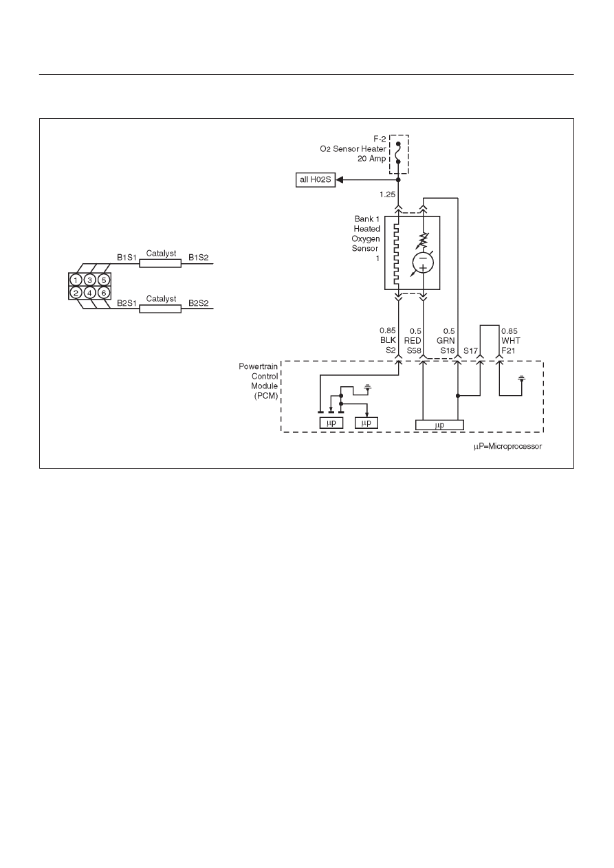
P0134 HO2S Circuit Insufficient Activity Bank 1 Sensor 1

D06R200013

Circuit Description

D

The powertrain control module (PCM) supplies a bias
voltage of about 450 mV between the heated oxygen
sensor (HO2S) high and low circuits.  When measured
with a 10 megaohm digital voltmeter, this may display
as low as 320 mV.  The oxygen sensor varies the
voltage within a range of about 1000 mV when the
exhaust is rich, down through about 10 mV when
exhaust is lean.  The PCM constantly monitors the
HO2S signal during “closed loop” operation and
compensates for a rich or lean condition by decreasing
or increasing injector pulse width as necessary.  If the
Bank 1 HO2S 1 voltage remains at or near the 450 mV
bias for an extended period of time, DTC P0134 will be
set, indicating an open sensor signal or sensor low
circuit.

D

Heated oxygen sensors are used to minimize the
amount of time required for “closed loop” fuel control
operation and to allow accurate catalyst monitoring.
The oxygen sensor heater greatly decreases the
amount of time required for fuel control sensors Bank
1 HO2S 1 and Bank 2 HO2S 1 to become active.

D

Oxygen sensor heaters are required by post-catalyst
monitor sensors to maintain a sufficiently high
temperature for accurate exhaust oxygen content
readings further from the engine.

Conditions for Setting the DTC

D

No related DTCs.

D

Battery voltage is above 10 volts.

D

The engine has been running for over 5 seconds.

D

Engine coolant temperature (ETC) is above 60

°

C

(140

°

F).

D

Oxygen sensor heater has been determined to be
functioning properly.

D

Bank 1 HO2S 1 signal voltage remains between
400 mV and 500 mV for a total of 77 seconds over a
90-second period of time.

Action Take When the DTC Sets

D

The PCM will ON the MIL after second trip with
detected fault.

D

The PCM will store conditions which were present
when the DTC was set as Freeze Frame and in the
Failure Records data.

D

“Open loop” fuel control will be in effect.

Conditions for Clearing the MIL/DTC

D

The PCM will turn the MIL “OFF” on the third
consecutive trip cycle during which the diagnostic has
been run and the fault condition is no longer present.

D

A history DTC P0134 will clear after 40 consecutive
warm-up cycles have occurred without a fault.

D

DTC P0134 can be cleared by using the Tech 2 “Clear
Info” function or by disconnecting the PCM battery
feed.

6E–167

6VE1 3.5L ENGINE DRIVEABILITY AND EMISSIONS

Diagnostic Aids

Check for the following conditions:

D

Poor connection or damaged harness – Inspect the
harness connectors for backed-out terminals,
improper mating, broken locks, improperly formed or
damaged terminals, poor terminal-to-wire connection,
and damaged harness.

D

Faulty HO2S heater or heater circuit – With the ignition
“ON”, engine “OFF”, after a cool down period, the
HO2S 1 voltage displayed on the Tech 2 is normally
455-460 mV.  A reading over 1000 mV indicates a
signal line shorted to voltage.  A reading under 5 mV
indicates a signal line shorted to ground or signal lines
shorted together.  Disconnect the HO2S and connect
a test light between the HO2S ignition feed and heater
ground circuits.  If the test light does not light for 2
seconds when the ignition is turned on, repair the open
ignition feed or sensor ground circuit as necessary.  If
the test light lights and the HO2S signal and low circuits
are OK, replace the HO2S.

D

Intermittent test – With the Ignition “ON”, monitor the
HO2S signal voltage while moving the wiring harness
and related connectors.  If the fault is induced, the
HO2S signal voltage will change.  This may help isolate
the location of the malfunction.

Test Description

Number(s) below refer to the step number(s) on the
Diagnostic Chart.
3. If the DTC P0134 test passes while the Failure

Records conditions are being duplicated, an
intermittent conditions is indicated.

Reviewing the Failure Records vehicle mileage since the
diagnostic test last failed may help determine how often
the condition that caused the DTC to be set occurs.  This
may assist in diagnosing the condition.

DTC P0134 –HO2S Circuit  Insufficient Activity Bank 1 Sensor 1


Step

Action

Value(s)

Yes

No

1

Was the “On-Board Diagnostic (OBD) System Check”
performed?

Go to 

Step 2

Go to 

OBD

System

Check

2

1. Install the Tech 2.
2. Run the engine at operating temperature.
3. Operate the engine above 1200 RPM for two

minutes.

Does the Tech 2 indicate Bank 1 HO2S 1 voltage
varying outside the specified values?

400-500 mV

Go to 

Step 3

Go to 

Step 4

3

1. Ignition “ON”, engine “OFF”, review and record

Tech 2 Failure Records data and note parameters.

2. Operate the vehicle within Failure Records

conditions as noted.

3. Using a Tech 2, monitor “DTC” info for DTC P0134

until the DTC P0134 test runs.

4. Note the test result.

Does the Tech 2 indicate DTC P0134 failed this
ignition?

Go to 

Step 4

Check the

Procedure

Refer to

Diagnostic

Aids

4

Check for a damaged harness.

Was a problem found?

Verify repair

Go to 

Step 5

5

Check for poor Bank 1 HO2S 1 high and low circuit
terminal connections at the Bank 1 HO2S 1 harness
connector and replace terminal(s) if necessary.

Did any terminals require replacement?

Verify repair

Go to 

Step 6

6

Check for poor Bank 1 HO2S 1 high and low circuit
terminal connections at the PCM and replace terminals
if necessary.

Did any terminals require replacement?

Verify repair

Go to 

Step 7

6E–168

6VE1 3.5 ENGINE DRIVEABILITY AND EMISSIONS

DTC P0134 –HO2S Circuit  Insufficient Activity Bank 1 Sensor 1

  (Cont'd)

Step

No

Yes

Value(s)

Action

7

1. Ignition “OFF”.
2. With the PCM disconnected, check continuity of the

Bank 1 HO2S 1 high circuit.

3. If the Bank 1 HO2S 1 high circuit measures over 5.0

ohms, repair open or poor connection as necessary.

Was a Bank 1 HO2S 1 high circuit problem found and
corrected?

Verify repair

Go to 

Step 8

8

1. Ignition “OFF”.
2. With the PCM disconnected, check continuity of the

Bank 1 HO2S 1 low circuit.

3. If the Bank 1 HO2S 1 low circuit measures over 5

ohms, repair open or poor connection as necessary.

Was a Bank 1 HO2S 1 low circuit problem found and
corrected?

Verify repair

Go to 

Step 9

9

1. Ignition “ON”, engine “OFF”.
2. Disconnect Bank 1 HO2S 1 and jumper the HO2S

high and low circuits (PCM side) to ground.

3. Using a Tech 2, monitor Bank 1 HO2S 1 voltage.

Is Bank 1 HO2S 1 voltage in the specified range?

0-10 mV

Go to 

Step 10

Go to 

Step 11

10

Replace Bank 1 HO2S 1.

Is the action complete?

Verify repair

11

Replace the PCM.

IMPORTANT: The replacement PCM must be
programmed.  Refer to 

On-Vehicle Service in

Powertrain Control Module and Sensors for
procedures.

And also refer to latest Service Bulletin.

Check to see if the Latest software is released or not.
And then Down Load the LATEST PROGRAMMED
SOFTWARE to the replacement PCM.

Is the action complete?

Verify repair

6E–169

6VE1 3.5L ENGINE DRIVEABILITY AND EMISSIONS

Diagnostic Trouble Code (DTC) 

P0135 HO2S Heater Circuit Bank 1 Sensor 1

D06R200013

Circuit Description

Heated oxygen sensors are used to minimize the amount
of time required for “closed loop” fuel control operation
and to allow accurate catalyst monitoring.  The oxygen
sensor heater greatly decreases the amount of time
required for fuel control sensors Bank 1 HO2S 1 and Bank
2 HO2S 1 to become active.  Oxygen sensor heaters are
required by post-catalyst monitor sensors  to maintain a
sufficiently high temperature which allows accurate
exhaust oxygen content readings further from the engine.
The powertrain control module (PCM) will run the heater
test only after a cold start (determined by engine coolant
and intake air temperature at the time of start-up) and only
once during an ignition cycle.  When the engine is started
the PCM will monitor the HO2S voltage.  When the HO2S
voltage indicates a sufficiently active sensor, the PCM
looks at how much time has elapsed since start-up.  If the
PCM determines that too much time was required for the
Bank 1 HO2S 1 to become active, a DTC P0135 will set.
The time it should take the HO2S to reach operating
temperature is based on the accumulated amount of air
that has passed through the MAF sensor and into the
engine (more accumulated air flow = shorter time to
HO2S activity).

Conditions for Setting the DTC

D

The engine has been running for over 120 seconds.

D

Heater signal is below 0.1A.

D

Bank 1 HO2S 1 voltage does not change more than
150 mV from the bias voltage (between 400 mV and
500 mV) for a longer amount of time than it should.  The
maximum amount of time to come up to operating
range is 150 seconds.  This warm-up time depends on
the engine coolant temperature at start-up and
accumulate air flow since start-up.

Action Taken When the DTC Sets

D

The PCM will illuminate the malfunction indicator lamp
(MIL) after the second consecutive trip in which the
fault is detected.

D

The PCM will store conditions which were present
when the DTC was set as Freeze Frame and in the
Failure Records data.

Conditions for Clearing the MIL/DTC

D

The PCM will turn the MIL “OFF” on the third
consecutive trip cycle during which the diagnostic has
been run and the fault condition is no longer present.

D

A history DTC P0135 will clear after 40 consecutive
warm-up cycles have occurred without a fault.

D

DTC P0135 can be cleared by using the Tech 2 “Clear
Info” function or by disconnecting the PCM battery
feed.

Diagnostic Aids

Check for the following conditions:


Content   ..  447  448  449  450   ..