Isuzu Trooper (1998-2002 year). Manual - part 350
6E–313
ENGINE DRIVEABILITY AND EMISSIONS
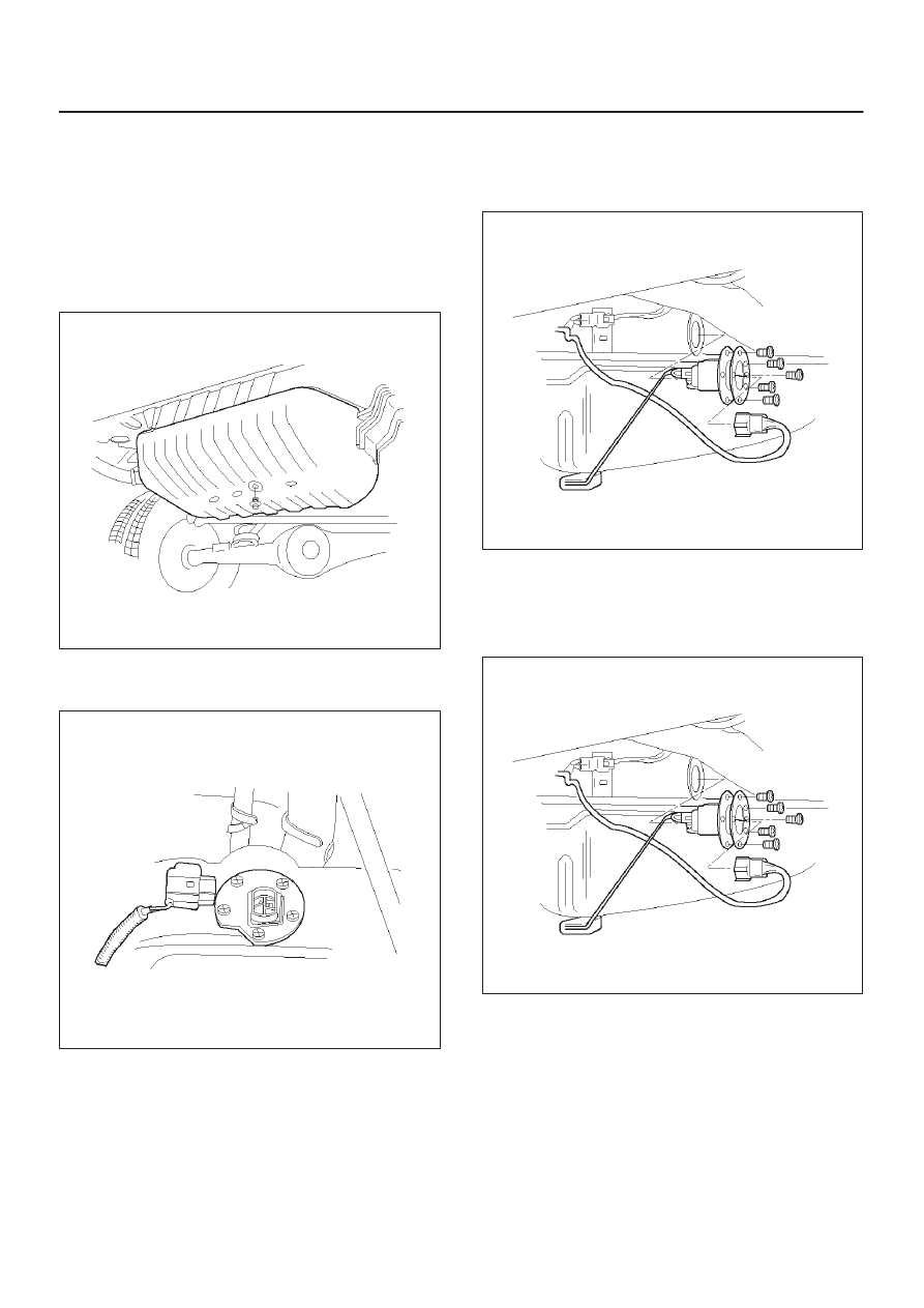
Fuel Gauge Unit
Removal Procedure
1. Disconnect the negative battery cable.
2. Loosen the fuel filler cap.
3. Drain the fuel from the tank.
Tighten
D
Tighten the drain plug to 20 N·m (14 lb ft.).
TS22907
4. Disconnect the wiring connector from the fuel gauge
unit.
TS23771
5. Remove the fuel gauge unit retaining screws.
6. Remove the fuel gauge unit.
D
Cover or plug the fuel tank to prevent dust, dirt, or
debris from entering the tank.
TS22911
Installation Procedure
1. Install the fuel gauge unit.
2. Install the fuel gauge unit retaining screws.
TS22911