Isuzu Trooper (1998-2002 year). Manual - part 238


  Index      Isuzu     Isuzu Trooper - service repair manual 1998-2002 year


Search            


Content   ..  236  237  238  239   ..


Isuzu Trooper (1998-2002 year). Manual - part 238


6A–26

ENGINE MECHANICAL

Exhaust Manifold LH

Removal

1. Disconnect battery ground cable.
2. Remove air cleaner duct assembly.
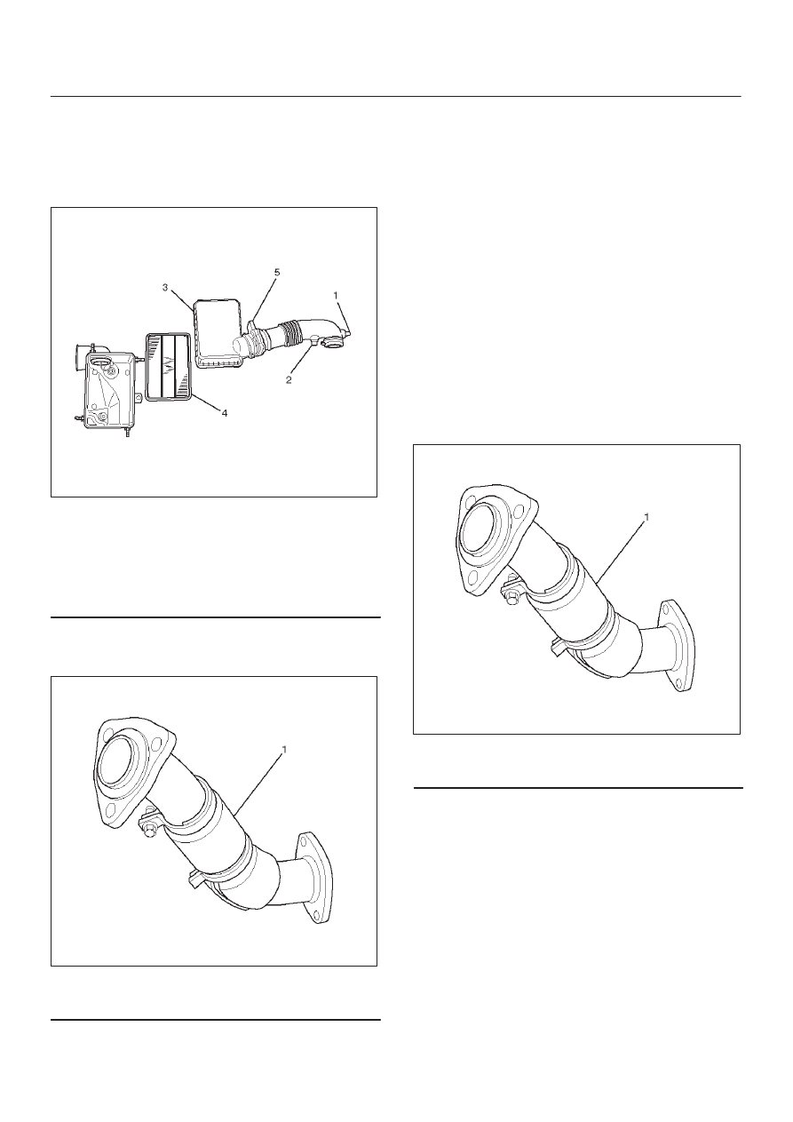
130RW001

Legend

(1) Positive Crankcase Ventilation Hose Connector
(2) Intake Air Temperature Sensor
(3) Air Cleaner Duct Assembly
(4) Air Cleaner Element
(5) Mass Air Flow Sensor

3. Remove exhaust front pipe three stud nuts from

exhaust side and two nuts from rear end of exhaust
front pipe.

150RW062

Legend

(1) Exhaust Front Pipe LH

4. Remove heat protector two fixing bolts then the heat

protector.

5. Remove a bolt on engine LH side for air conditioner

(A/C) compressor bracket and loosen two bolts for
A/C compressor then move A/C compressor to front
side.

6. Remove exhaust manifold eight fixing nuts and

remove exhaust manifold from the engine.

Installation

1. Install exhaust manifold and tighten exhaust manifold

fixing nuts to the specified torque with new nuts.

Torque: 57 N·m (5.8 Kg·m/42 lb ft)

2. Install heat protector.
3. Install exhaust front pipe and tighten three stud nuts

and two nuts to the specified torque.

Torque : 
Stud nuts: 67 N·m (6.8 Kg·m/49 lb ft)
Nuts: 43 N·m (4.4 Kg·m/32 lb ft)

150RW062

Legend

(1) Exhaust Front Pipe LH

4. Set A/C compressor to normal position and tighten

two bolts and a bolt to the specified torque.

Torque : 40 N·m (4.1 Kg·m/30 lb ft)

5. Install air cleaner duct assembly.

6A–27

ENGINE MECHANICAL

Exhaust Manifold RH

Removal

1. Disconnect battery ground cable.
2. Remove torsion bar. Refer to removal procedure in

Front Suspension section.

3. Remove exhaust front pipe three stud nuts and two

nuts then disconnect exhaust front pipe.

150RW061

Legend

(1) Exhaust Front Pipe RH
(2) O

2

 Sensor (for IGM)

4. Remove heat protector two fixing bolts then the heat

protector.

5. Remove exhaust gas recirculation (EGR) pipe fixing

bolt and nut from exhaust manifold, remove a nut
from EGR valve and a bolt from rear side of cylinder
head for bracket of EGR pipe then remove the EGR
pipe.

056RW001

Legend

(1) Exhaust Gas Recirculation (EGR) Valve
(2) EGR Pipe

6. Remove exhaust manifold eight fixing nuts then the

exhaust manifold.

Installation

1. Install exhaust manifold and tighten bolts to the

specified torque.

Torque : 57 N·m (5.8 Kg·m/42 lb ft)

2. Install the EGR pipe, tighten bolt and nut on exhaust

manifold to specified torque.

Torque : 28 N·m (2.9 Kg·m/21 lb ft)

Tighten nut to EGR valve to the specified torque.

Torque : 44 N·m (4.5 Kg·m/33 lb ft)

Tighten the bolt for EGR pipe bracket to specified
torque.

Torque : 25 N·m (2.5 Kg·m/18 lb ft)

3. Install heat protector
4. Install exhaust front pipe and tighten three stud nuts

and two nuts to the specified torque.

Torque:
Stud nuts: 67 N·m (6.8 Kg·m/49 lb ft)
Nuts: 43 N·m (4.4 Kg·m/32 lb ft)

5. Install the torsion bar and readjust the vehicle height.

Refer to installation and vehicle height adjustment
procedure for Front Suspension.

6A–28

ENGINE MECHANICAL

Crankshaft Pulley

Removal

1. Disconnect battery ground cable.
2. Remove air cleaner assembly.

130RW001

Legend

(1) Positive Crankcase Ventilation Hose Connector
(2) Intake Air Temperature Sensor
(3) Air Cleaner Duct Assembly
(4) Air Cleaner Element
(5) Mass Air Flow Sensor

3. Remove radiator upper fan shroud from radiator.
4.  Move serpentine belt tensioner to loose side using

wrench then remove serpentine belt.

850RW001

Legend

(1) Crankshaft Pulley
(2) Cooling Fan Pulley
(3) Tensioner
(4) Generator
(5) Air Conditioner Compressor
(6) Power Steering Oil Pump
(7) Serpentine Belt

5. Remove cooling fan assembly four fixing nuts, then

the cooling fan assembly.

6. Remove crankshaft pulley assembly using J-8614-01

crankshaft holder, hold crankshaft pulley then
remove center bolt and pulley.

Installation

1. Install crankshaft pulley using J-8614-01 crankshaft

holder, hold the crankshaft pulley and tighten center
bolt to the specified torque.

Torque : 167 N·m (17.0 Kg·m/123 lb ft)

2. Install cooling fan assembly and tighten bolts/nuts to

the specified torque.

Torque : 22 N·m (2.2 Kg·m/16 lb ft) for fan pulley
and fan bracket.

Torque : 10 N·m (1.0 Kg·m/88.5 lb in) for fan and
clutch assembly.

3. Move serpentine belt tensioner to loose side using

wrench, then install serpentine belt to normal
position.

4. Install radiator upper fan shroud.
5. Install air cleaner assembly.

6A–29

ENGINE MECHANICAL

Timing Belt

Removal

1. Disconnect battery ground cable.
2. Remove air cleaner assembly.
3. Remove radiator upper fan shroud from radiator.
4. Move drive belt tensioner to loose side using wrench

then remove drive belt.

850RW001

Legend

(1) Crankshaft Pulley
(2) Cooling Fan Pulley
(3) Tensioner
(4) Generator
(5) Air Conditioner Compressor
(6) Power Steering Oil Pump
(7) Drive Belt

5. Remove cooling fan assembly four nuts, then the

cooling fan assembly.

6. Remove cooling fan drive pulley assembly.
7. Remove idle pulley assembly.
8. Remove serpentine belt tensioner assembly.
9. Remove power steering pump assembly.

10. Remove crankshaft pulley assembly using

5–8840–0133–0 crankshaft holder, hold crankshaft
pulley remove center bolt, then the pulley.

11. Remove right side timing belt cover then left side

timing belt cover.

12. Remove lower timing belt cover
13. Remove pusher.

CAUTION: The pusher prevents air from entering
the oil chamber. Its rod must always be facing
upward.

014RW011

Legend

(1) Up Side
(2) Down Side
(3) Direction For Installation
(4) Locking Pin

14. Remove timing belt.

CAUTION:
1. Do not bend or twist the belt, otherwise its core

could be damaged. The belt should not be bent at
a radius less than 30 mm.

2. Do not allow oil or other chemical substances to

come in contact with the belt. They will shorten
the life.

3. Do not attempt to pry or stretch the belt with a

screw driver or any other tool during installation.

4. Store timing belt in a cool and dark place. Never

expose the belt direct sunlight or heat.


Content   ..  236  237  238  239   ..