Isuzu Trooper (1998-2002 year). Manual - part 226


  Index      Isuzu     Isuzu Trooper - service repair manual 1998-2002 year


Search            


Content   ..  224  225  226  227   ..


Isuzu Trooper (1998-2002 year). Manual - part 226


5C – 56 POWER ASSISTED BRAKE SYSTEM
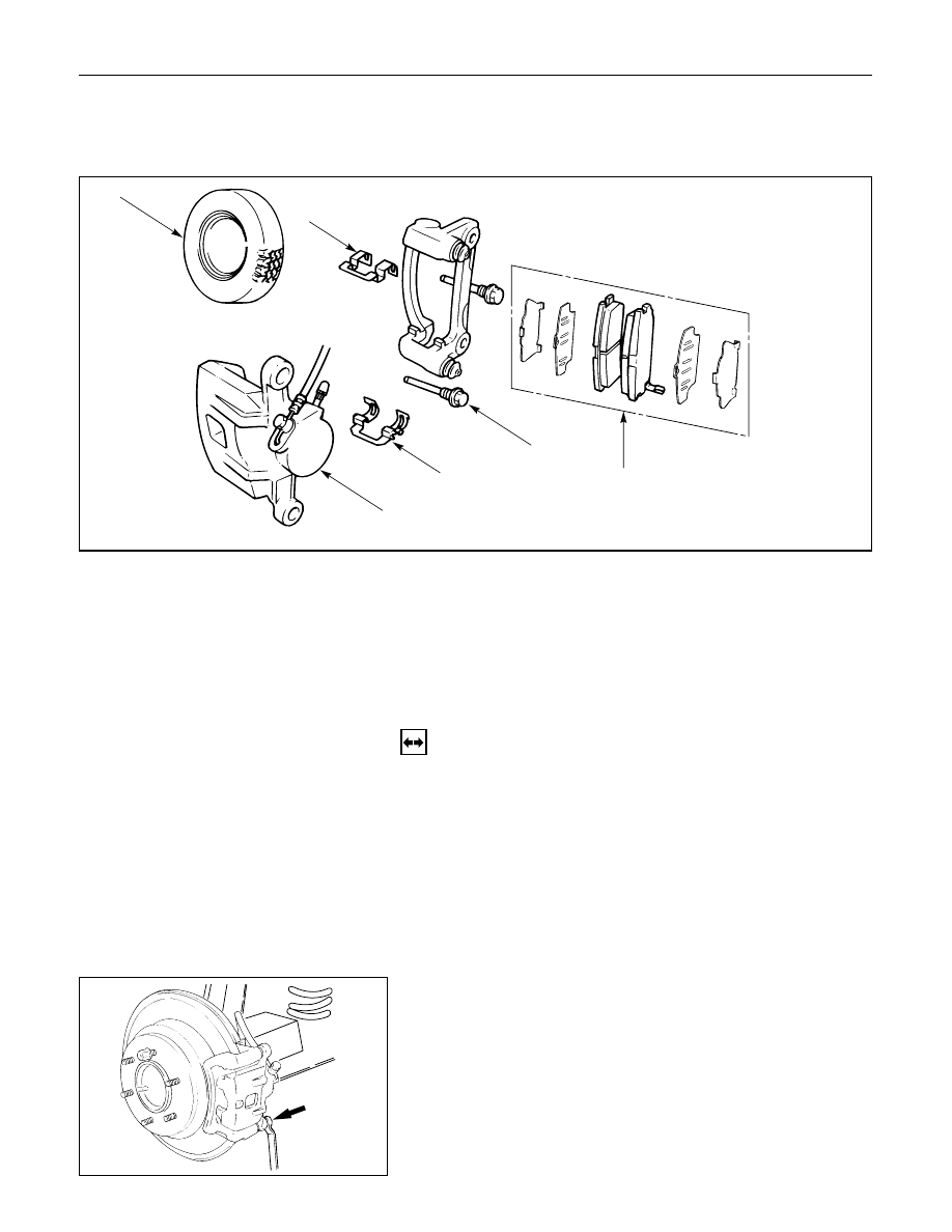
REAR DISC BRAKE

BRAKE PADS REPLACEMENT

1

5

5

3

2

4

Removal Steps

1.

Wheel and tire assembly

2.

Lock bolt

3.

Caliper assembly

4.

Pad assembly with shim

5.

Clip

Installation Steps

To install, follow the removal steps in the
reverse order.

REMOVAL

NOTE:
If a squealing noise occurs from the rear brake while
driving, check the pad wear indicator plate. If the
indicator plate contacts the rotor, the disc pad
assembly should be replaced.
1) Draw out two-thirds of the brake fluid from the

reservoir.

2) Raise the vehicle and support it with suitable

safety stands.

1. Wheel and Tire Assembly

Refer to Wheels and Tires in Suspension section.

2. Lock Bolt

POWER ASSISTED BRAKE SYSTEM  5C – 57

3. Caliper Assembly

Support the caliper assembly so that the brake
hose is not stretched or damaged.

4. Pad Assembly with Shim

5. Clip

INSTALLATION

5. Clip

Clip

4. Pad Assembly with Shim

Apply special grease (approx. 0.2 g) to both
contacting surfaces of inner shims. Wipe off
extruded grease after installing.

Inner shim

Wear indicator

Apply
special
grease

3. Caliper Assembly

1) Use adjustable pliers to bottom the piston into the

caliper bore. Be careful not to damage the piston
dust boot.

2) Do not damage the flexible hose by twisting or

pulling it.

5C – 58 POWER ASSISTED BRAKE SYSTEM

2. Lock Bolt

Lock Bolt Torque

N·m (kg·m / lb·ft)

44 (4.5 / 32)

1. Wheel and Tire Assembly

1) Refer to Wheels and Tires in Suspension section.
2) Pump the brake pedal several times to make sure

that the pedal is firm. Check the brake fluid level
in the reservoir after pumping the brakes.

POWER ASSISTED BRAKE SYSTEM  5C – 59

CALIPER REPLACEMENT

7

1

4

6

8

8

5

2

3

Removal Steps

1.

Wheel and tire assembly

2.

Brake flexible hose

3.

Lock bolt

4.

Guide bolt

5.

Caliper assembly

6.

Support bracket

7.

Pad assembly with shim

8.

Clip

Installation Steps

To install, follow the removal steps in the
reverse order.

REMOVAL

Raise the vehicle and support with suitable safety
stands.

1. Wheel and Tire Assembly

Refer to Wheels and Tires in Suspension section.

2. Brake Flexible Hose

1) Remove the bolt and gaskets, then disconnect the

flexible hose from the caliper.

2) After disconnecting the flexible hose, cap or tape

the openings to prevent entry of foreign material.

3) Since the brake fluid flows out from the

connecting coupler, place a drain pan under the
vehicle.


Content   ..  224  225  226  227   ..