Isuzu Trooper (1998-2002 year). Manual - part 212


  Index      Isuzu     Isuzu Trooper - service repair manual 1998-2002 year


Search            


Content   ..  210  211  212  213   ..


Isuzu Trooper (1998-2002 year). Manual - part 212


5B–6

ANTI–LOCK BRAKE SYSTEM

Rear Wheel Speed Sensor

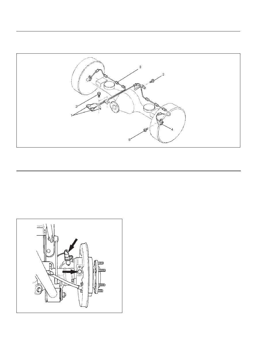
Rear Wheel Speed Sensor and Associated Parts

350RW008

Legend

(1) Speed Sensor Connector
(2) Sensor Cable Fixing Bolt

(3) Clip (11 pieces)
(4) Speed Sensor
(5) Sensor Fixing Bolt

Removal

1. Remove speed sensor connector.
2. Remove clip.
3. Remove sensor cable fixing bolt.
4. Remove sensor fixing bolt.
5. Remove speed sensor.

350RS035

Inspection and Repair

1. Check the speed sensor pole piece for presence of

foreign materials; remove any dirt, etc.

2. Check the pole piece for damage, and replace the

speed sensor if necessary.

3. Check the speed sensor cable for a short or an open,

and replace with a new one if necessary.  To check for
cable short or open, bend or stretch the cable while
checking for continuity.

4. Check the sensor ring for damage including tooth

chipping. If damaged replace the axle shaft assembly.
Refer to Front Hub and Disc in Drive Shaft System
section.

Installation

1. Install the speed sensor and take care not to hit the

speed sensor pole piece during installation.

2. Install the sensor fixing bolt and tighten it to the

specified torque.

Torque : 18 N·m (1.8kg·m/13 lb ft)

3. Install the sensor cable fixing bolt and tighten it to the

specified torque.

Torque : 24 N·m (2.4kg·m/18 lb ft)

NOTE: Confirm that the cable is not twisted when
connecting the speed sensor cable.

4. Install clip.
5. Install speed sensor connector.

POWER ASSISTED BRAKE SYSTEM  5C – 1

SECTION 5C

POWER ASSISTED BRAKE SYSTEM

CONTENTS

PAGE

Service Precaution ............................................................................................................. 5C- 2

Brake System Diagnosis .................................................................................................... 5C- 3

Troubleshooting ................................................................................................................. 5C- 5

Main Data and Specifications ........................................................................................... 5C- 7

Service Standard ................................................................................................................ 5C-  8

Servicing ............................................................................................................................. 5C-  9

Fixing Torque ...................................................................................................................... 5C-18

Special Tools....................................................................................................................... 5C-21

General Description ........................................................................................................... 5C-22

Master Cylinder.............................................................................................................. 5C-22

Vacuum Booster..............................................................................................................5C-23

Disc Brakes ..................................................................................................................... 5C-24

On-Vehicle Service ............................................................................................................. 5C-25

Brake Hose Replacement .............................................................................................. 5C-25

Brake Pipe Replacement ............................................................................................... 5C-27

P & B Valve ..................................................................................................................... 5C-28

P & B Valve Replacement .............................................................................................. 5C-29

Load Sensing Proportioning Valve (LSPV) .................................................................. 5C-30

Brake Pedal Replacement ............................................................................................. 5C-34

Stoplight Switch Replacement..................................................................................... 5C-36

Fluid Reservoir Tank ...................................................................................................... 5C-38

Master Cylinder Assembly ............................................................................................ 5C-39

Vacuum Booster Assembly ........................................................................................... 5C-41

Exterior Components .................................................................................................... 5C-44

SECTION

5C – 2 POWER ASSISTED BRAKE SYSTEM

Front Disc Brakes ........................................................................................................... 5C-47

Brake Pads Replacement .......................................................................................... 5C-47

Caliper Replacement ................................................................................................. 5C-50

Rebuilding the Caliper............................................................................................... 5C-53

Rear Disc Brakes ............................................................................................................ 5C-56

Brake Pads Replacement .......................................................................................... 5C-56

Caliper Replacement ................................................................................................. 5C-59

Rebuilding the Caliper............................................................................................... 5C-62

Unit Repair .......................................................................................................................... 5C-65

Master Cylinder.............................................................................................................. 5C-65

Vacuum Booster............................................................................................................. 5C-67

SERVICE PRECAUTION

WARNING: 
IF SO EQUIPPED WITH A SUPPLEMENTAL RESTRAINT SYSTEM (SRS), REFER TO THE SRS COMPONENT
AND WIRING LOCATION VIEW IN ORDER TO DETERMINE WHETHER YOU ARE PERFORMING SERVICE ON
OR NEAR THE SRS COMPONENTS OR THE SRS WIRING. WHEN YOU ARE PERFORMING SERVICE ON OR
NEAR THE SRS COMPONENTS OR THE SRS WIRING, REFER TO THE SRS SERVICE INFORMATION.
FAILURE TO FOLLOW WARNINGS COULD RESULT IN POSSIBLE AIR BAG DEPLOYMENT, PERSONAL
INJURY, OR OTHERWISE UNNEEDED SRS SYSTEM REPAIRS.

CAUTION:
Always use the correct fastener in the proper location. When you replace a fastener, use ONLY the exact
part number for that application. ISUZU will call out those fasteners that require a replacement after
removal. ISUZU will also call out the fasteners that require thread lockers or thread sealant. UNLESS
OTHERWISE SPECIFIED, do not use supplemental coatings (Paints, greases, or other corrosion inhibitors)
on threaded fasteners or fastener joint interfaces. Generally, such coatings adversely affect the fastener
torque and the joint clamping force, and may damage the fastener. When you install fasteners, use the
correct tightening sequence and specification. Following these instructions can help you avoid damage to
parts and systems.

POWER ASSISTED BRAKE SYSTEM  5C – 3

BRAKE SYSTEM DIAGNOSIS

ROAD TESTING THE BRAKES

Brake Test

Brakes should be tested on a dry, clean, reasonably
smooth and level roadway. A true test of brake
performance cannot be made if the roadway is wet,
greasy or covered with loose dirt so that all tires do
not grip the road equally. Testing will also be
adversely affected if the roadway is crowned so as to
throw the weight of the vehicle toward wheels on one
side or if the roadway is so rough that wheels tend to
bounce. Test the brakes at different vehicle speeds
with both light and heavy pedal pressure; however,
avoid locking the wheels and sliding the tires. Locked
wheels and sliding tires do not indicate brake
efficiency, since heavily braked but turning wheels
will stop the vehicle in less distance than locked
wheels. More tire-to-road friction is present with a
heavily braked turning tire then with a sliding tire.
The standard brake system is designed and balanced
to avoid locking the wheels except at very high
deceleration levels.
It is designed this way because the shortest stopping
distance and best control is achieved without brake
lock-up.
Because of high deceleration capability, a firmer pedal
may be felt at higher deceleration levels.

External Conditions That Affect Brake 
Performance

1. Tires: Tires having unequal contact and grip on the

road will cause unequal braking. Tires must be
equally inflated, identical in size, and the tread
pattern of right and left tires must be
approximately equal.

2. Vehicle loading: A heavily loaded vehicle requires

more braking effort.

3. Wheel Alignment: Misalignment of the wheels,

particularly in regard to excessive camber and
caster, will cause the brakes to pull to one side.

BRAKE FLUID LEAKS

With engine running at idle and the transmission in
“Neutral”, depress the brake pedal and hold a
constant foot pressure on the pedal. If pedal gradually
falls away with the constant pressure, the hydraulic
system may be leaking.
Check the master cylinder fluid level. While a slight
drop in reservoir level will result from normal lining
wear, an abnormally low level in resevoir indicates a
leak in the system. The hydraulic system may be
leaking internally as well as externally. Refer to
“Master Cylinder Inspection”. Also, the system may
appear to pass this test but still have slight leakage. If
fluid level is normal, check the vacuum booster push


Content   ..  210  211  212  213   ..