Index Isuzu Isuzu Trooper - service repair manual 1998-2002 year
Search
Content .. 153 154 155 156 ..
Isuzu Trooper (1998-2002 year). Manual - part 155
4B2–107
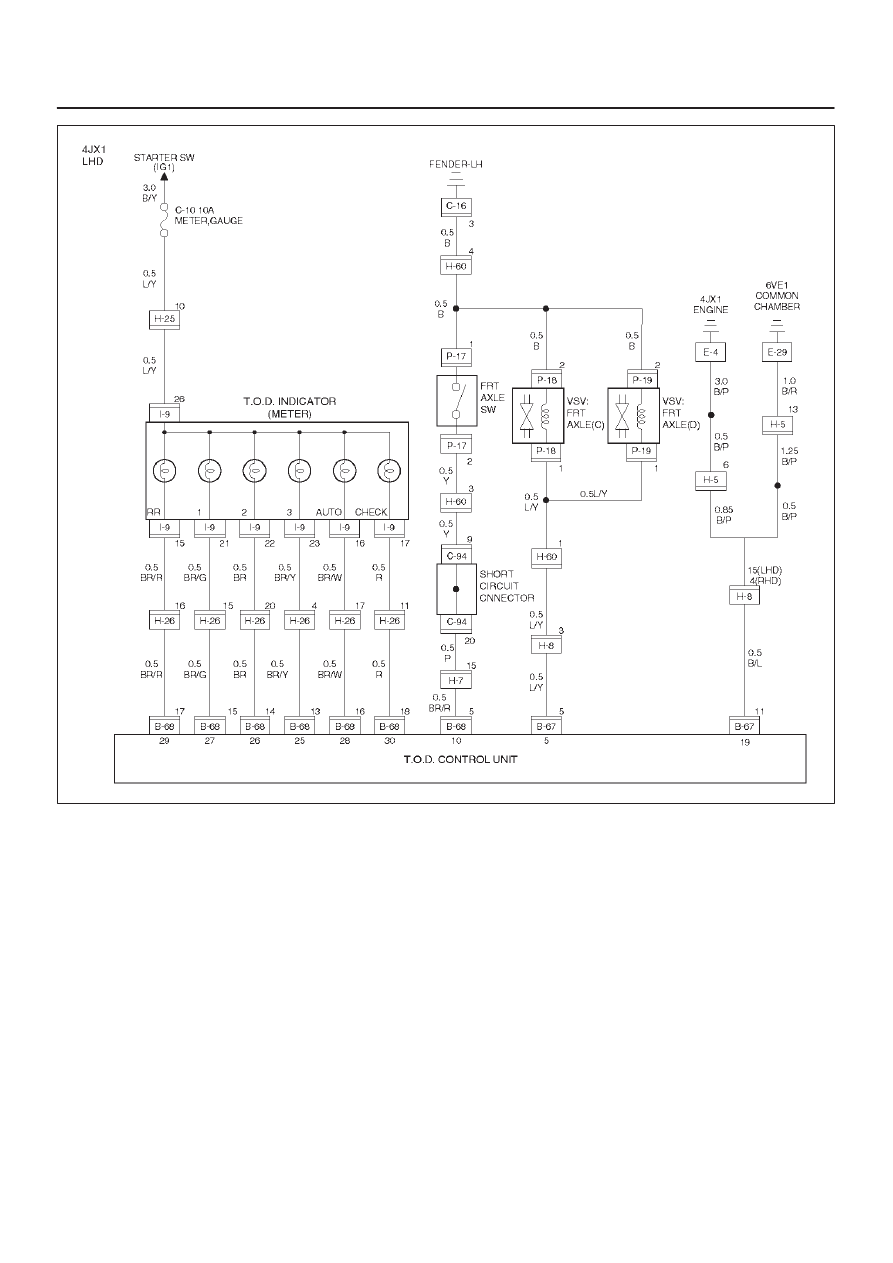
DRIVE LINE CONTROL SYSTEM (TOD)
D04RY00071