Isuzu Trooper (1998-2002 year). Manual - part 1090


  Index      Isuzu     Isuzu Trooper - service repair manual 1998-2002 year


Search            


Content   ..  1088  1089  1090  1091   ..


Isuzu Trooper (1998-2002 year). Manual - part 1090


SUPPLEMENTAL RESTRAINT SYSTEM

9J–47

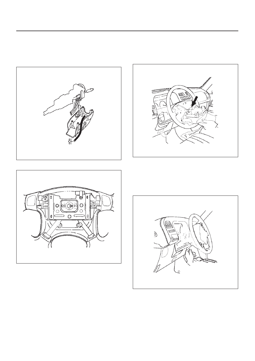
12. Install steering column cover.

CAUTION: When installing the steering column
cover, be sure to wire (through each harness) as
illustrated so that the harness starter switch,
combination switch and SRS coil may not catch
wiring.

825RS048

13. Install the steering wheel and align the setting marks.

430RS004

14. Tighten the steering wheel fixing nut to the specified

torque.

Torque: 34 N·m (3.5 Kg·m/25 Ib ft)

15. Connect horn lead.
16. Connect air bag wiring harness connector.

NOTE: Pass the lead wire through the tabs on the plastic
cover (wire protector) of air bag to prevent lead wire from
being pinched.

827RT009

17. Install air bag into steering wheel and tighten bolts to

specified sequence as shown in figure.

Torque: 8 N·m (0.8 Kg·m/69 Ib in)

CAUTION: Never use the air bag assembly from
another vehicle. Use only the air bag assembly
proper to the Trooper which is being repaired.

827RT008

18. Enable the SRS (Refer to “Enabling the SRS” in this

section).

SUPPLEMENTAL RESTRAINT SYSTEM

9J–48

Passenger Air Bag Assembly

Service Precautions

WARNING: SAFETY PRECAUTIONS MUST BE
FOLLOWED WHEN HANDLING A DEPLOYED AIR
BAG ASSEMBLY. AFTER DEPLOYMENT, THE AIR
BAG ASSEMBLY SURFACE MAY CONTAIN A SMALL
AMOUNT OF SODIUM HYDROXIDE, A BY–PRODUCT
OF THE DEPLOYMENT REACTION, THAT IS
IRRITATING TO THE SKIN AND EYES. MOST OF THE
POWER ON THE AIR BAG ASSEMBLY IS
HARMLESS. AS A PRECAUTION, WEAR GLOVES
AND SAFETY GLASSES WHEN HANDLING A
DEPLOYED AIR BAG ASSEMBLY, AND WASH YOUR
HANDS WITH MILD SOAP AND WATER
AFTERWARDS.

WARNING: WHEN CARRYING A LIVE AIR BAG
ASSEMBLY, MAKE SURE THE BAG AND TRIM
COVER ARE POINTED AWAY FROM YOU. NEVER
CARRY AIR BAG ASSEMBLY BY THE WIRES OR
CONNECTOR ON THE UNDERSIDE OF MODULE. IN
THE CASE OF AN ACCIDENTAL DEPLOYMENT, THE
BAG WILL THEN DEPLOY WITH MINIMAL CHANCE
OF INJURY. WHEN PLACING ALIVE AIR BAG
ASSEMBLY ON A BENCH OR OTHER SURFACE,
ALWAYS FACE BAG AND RIM COVER UP, AWAY
FROM THE SURFACE. NEVER REST A STEERING
COLUMN ASSEMBLY ON THE STEERING WHEEL
WITH THE AIR BAG ASSEMBLY FACE DOWN AND
COLUMN VERTICAL. THIS IS NECESSARY SO THAT
A FREE SPACE IS PROVIDED TO ALLOW THE AIR
BAG ASSEMBLY TO EXPAND IN THE UNLIKELY
EVENT OF ACCIDENTAL DEPLOYMENT.
OTHERWISE, PERSONAL INJURY COULD RESULT.

NOTE:  IN THE EVENT DEPLOYMENT HAS
OCCURRED, INSPECT COIL ASSEMBLY WIRE FOR
ANY SIGNS OF SCORCHING, MELTING OR ANY
OTHER DAMAGE DUE TO EXCESSIVE HEAT. IF THE
COIL HAS BEEN DAMAGED, REPLACE IT.

Removal

827RS001

1. Disable the SRS (Refer to “Disabling the SRS ” in this

section).

2. Remove gear control knob.
3. Remove front console assembly.
4. Remove rear console assembly and disconnect

harness connector.

5. Remove ECM and SDM cover.
6. Remove glove box assembly with lid.
7. Remove glove box cover.
8. Remove instrument panel assist side lower cover.
9. Disconnect engine hood opener lever.

10. Remove instrument panel door side lower cover.

11. Remove lower cluster with ashtray.

12. Remove meter cluster assembly and disconnect

harness connector.

13. Remove instrument panel lower center cover.
14. Disconnect passenger air bag assembly harness

connector.

15. Remove air bag assembly fixing bolts and nuts.
16. Remove passenger air bag assembly.

Installation

827RS001

1. Install passenger air bag assembly.
2. Install air bag assembly fixing bolts, nuts and tighten

to specified torque.

Torque: 6 N·m (0.6 Kg·m/52 Ib in)

3. Connect air bag assembly harness connector.
4. Install instrument panel lower center cover.
5. Install meter cluster assembly and connect harness

connector.

6. Install lower cluster with ashtray.
7. Install instrument panel door side lower cover.
8. Connect engine hood opener lever.
9. Install instrument panel assist side lower cover.

SUPPLEMENTAL RESTRAINT SYSTEM

9J–49

10. Install glove box cover.

11. Install glove box assembly with lid.

12. Install ECM and SDM cover.
13. Install rear console assembly and connect harness

connector.

14. Install front console assembly.
15. Install gear control knob.
16. Enable the SRS (Refer to “Enabling the SRS” in this

section).

Pretensioner Seat Belt (If so equipped)

Service Precaution

WARNING: WHEN PERFORMING SERVICE ON OR
AROUND THE PRETENSIONER SEAT BELT OR THE
PRETENSIONER SEAT BELT WIRING, FOLLOW THE
PROCEDURES LISTED BELOW TO TEMPORARILY
DISABLE THE PRETENSIONER SEAT BELT.
FAILURE TO FOLLOW PROCEDURES COULD
RESULT IN POSSIBLE THE PRETENSIONER SEAT
BELT DEPLOYMENT, PERSONAL INJURY OR
OTHERWISE UNNEEDED THE PRETENSIONER
SEAT BELT REPAIR.

AS A PRECAUTION, WEAR GLOVES AND SAFETY
GLASSES WHEN PERFORMING THE
PRETENSIONER SEAT BELT. WHEN DEPLOY A LIVE
PRETENSIONER SEAT BELT AT OUTSIDE THE
VEHICLE, DEPLOYMENT HARNESS SHALL REMAIN
SHORTED AND NOT BE CONNECTED TO A POWER
SOURCE UNTIL THE PRETENSIONER SEAT BELT IS
TO BE DEPLOYED. THE PRETENSIONER SEAT
BELT WILL IMMEDIATELY DEPLOY WHEN A POWER
SOURCE IS CONNECTED TO IT. CONNECTING THE
DEPLOYMENT HARNESS SHOULED ALWAYS BE
THE FINAL STEP IN THE PRETENSIONER SEAT
BELT DEPLOYMENT PROCEDURE. FAILURE TO
FOLLOW PROCEDURES IN THE ORDER LISTED
COULD RESULT IN PERSONAL INJURY.

Parts Location

760RW028

Legend

(1) Seat
(2) Pretensioner Cover
(3) Bolt
(4) Pretensioner Harness
(5) Pretensioner

Removal

1. Turn ignition switch to “LOCK”, remove key.
2. Remove the foot rest located behind the seat.
3. Remove the cover on seat slide.
4. Disconnect the 2-pin connector at the base of the

seat.

5. Remove four fixing bolts the seat slide and remove

seat.

6. Remove the pretensioner seat belt cover.
7. Remove the pretensioner seat belt assembly.

Installation

1. Install the pretensioner seat belt assembly.
2. Install the pretensioner seat belt cover.
3. Install the seat on seat slide and four fixing bolts.
4. Connect the yellow 2-pin connector at the base of the

seat.

5. Install the cover on seat slide.
6. Install the foot rest located behind the seat.

SUPPLEMENTAL RESTRAINT SYSTEM

9J–50

Main Data and Specifications

Fastener Tightening Specification

Application

N·m

Kg·m

Lb Ft

Lb In.

SDM

10

1.0

87

Driver air bag fixing bolt

8.8

0.9

78

Steering wheel fixing bolt

34

3.5

25

Steering column (dash panel side fixing bolts)

19

1.9

14

Steering column (Pedal bracket fixing bolt)

17

1.7

13

Steering column (Universal joint fixing bolt)

25

2.6

18

Passenger Air Bag fixing bolts and nuts

6

0.6

52


Content   ..  1088  1089  1090  1091   ..