Content .. 1022 1023 1024 1025 ..
Isuzu Trooper (1998-2002 year). Manual - part 1024
8F–24
BODY STRUCTURE
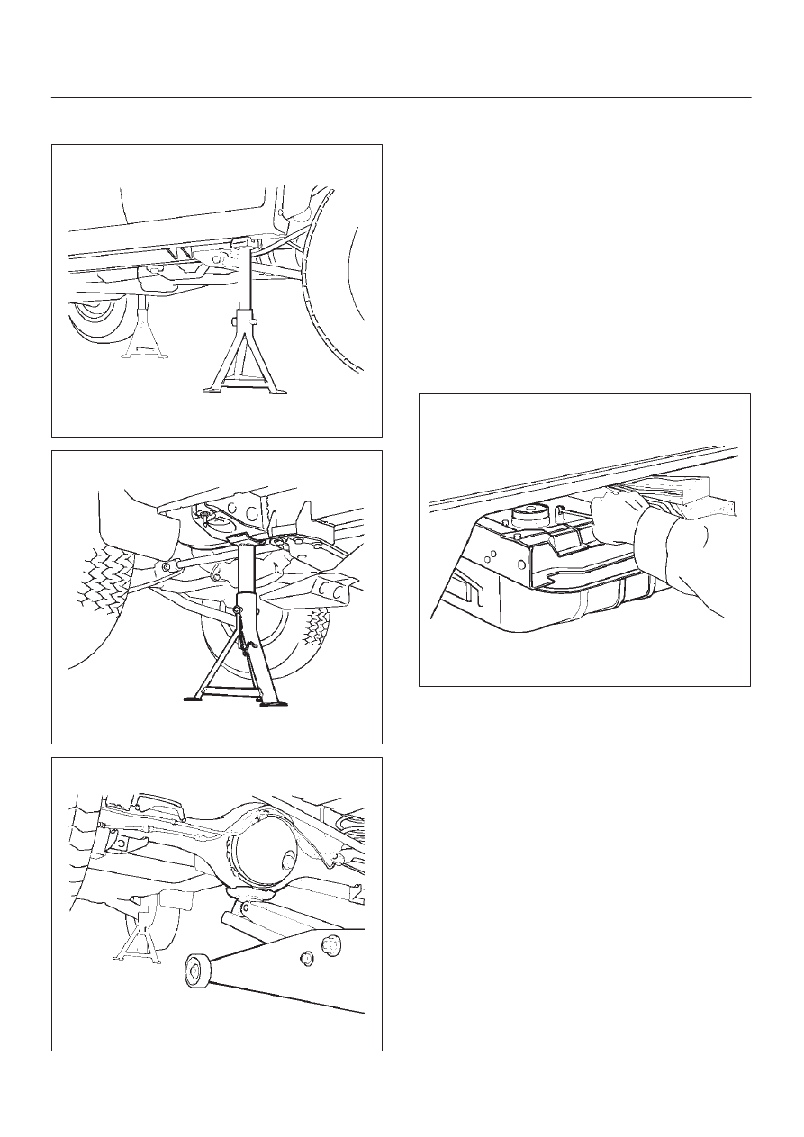
3. Support the rear side sill and frame stands, and
support the rear axle with a jack.
620RS002
501RS003
420RS002
4. Remove the mounting bolts (No. 3-6) on either side.
D
No. 3 (LWB only) — Remove the rear door sill plate
and center pillar lower-trim cover, turn over the floor
carpet and hold the bolt in check not to turn.
D
No. 4 (SWB) — Remove the luggage side trim
cover, turn over the floor carpet and hold the bolt in
check not to turn.
D
No. 4 (LWB) and No. 5 – 6
5. Remove the frame side mounting and washer.
6. Gently lower the jack supporting the rear axle until the
cab side mounting can be removed.
7. Remove the cab side mounting.
D
Be sure to use a splice bar around the mounting to
be removed.
D
As for No. 5 and 6, remove the frame side bracket
fixing bolts after lowering the frame gently.
510RS001
Installation
To install, follow the removal steps in the reverse order,
noting the following point:
1. Tighten each mounting bolt to the specified torque.
Torque : 50 N
•
m (5.1kg·m/37 lb ft)