Isuzu Trooper (1998-2002 year). Manual - part 37


  Index      Isuzu     Isuzu Trooper - service repair manual 1998-2002 year


Search            


Content   ..  35  36  37  38   ..


Isuzu Trooper (1998-2002 year). Manual - part 37


AIR CONDITIONING  1B–89
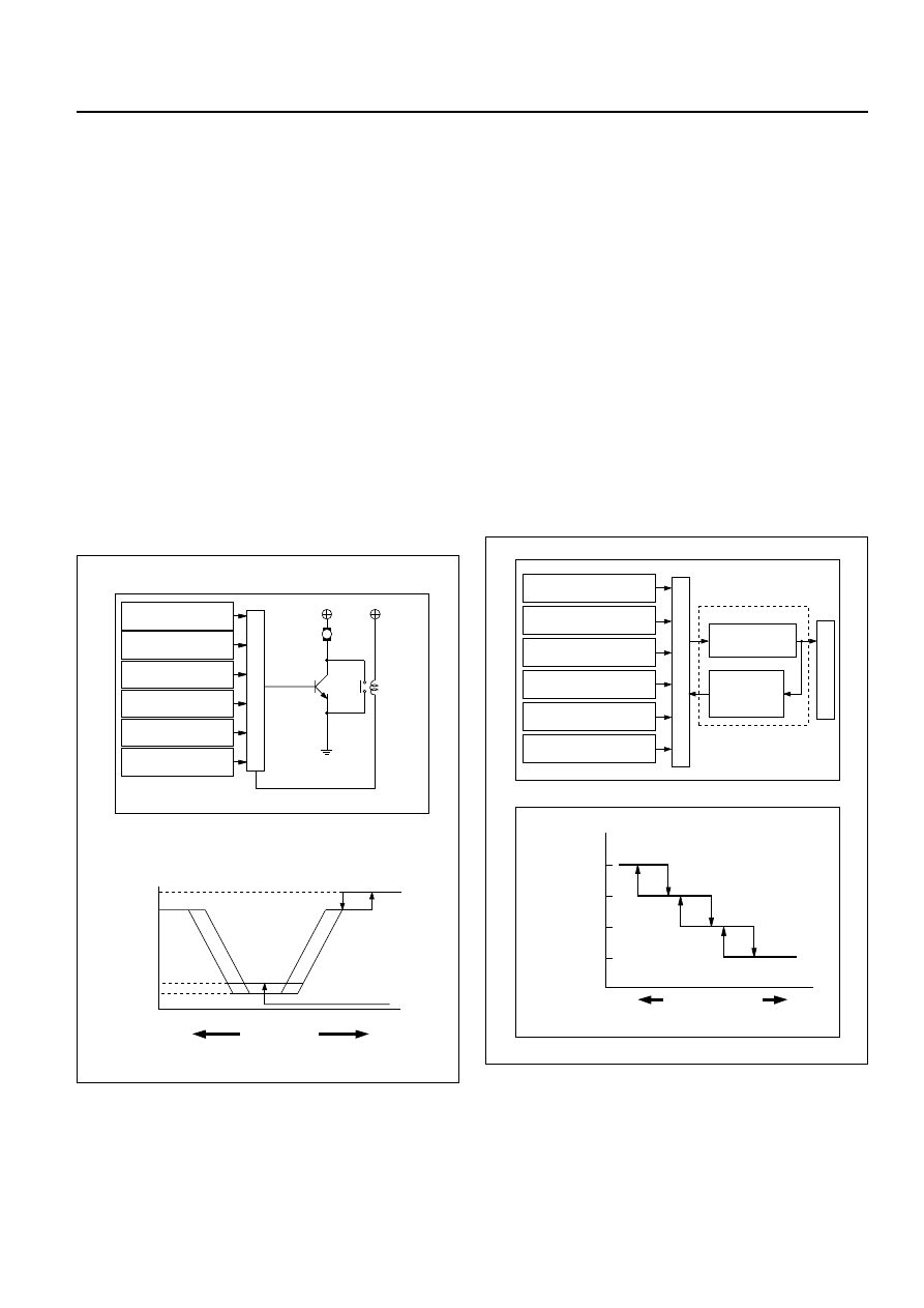
2. Air Flow Control

• In the Auto Mode

The automatic heater/air conditioner control unit
operates on the setup temperature signal and
other sensor signals to derive the total signal.
Then, the control unit adjusts base potential of
the power transistor to match it to the voltage
pattern of the target fan so that stage-less fan
speed control can be achieved.
When solar radiation quantity is detected in the
VENT or B/L mode, the control unit increases the
minimum fan voltage to offset.
When FH or FC is selected from the temperature
control switch, air flow is accordingly fixed to
MAX HI or AUTO HI.

• In the Manual Mode

Air flow specified from the fan switch is entered
to the automatic heater/air conditioner control
unit as the manual signal. The signal modifies
the air flow to the level specified from the fan
switch so that the required fan voltage is
attained.

3. Mode (Blow Port) Control

The automatic heater/air conditioner control unit
operates on the setup temperature from the
control switch, and temperature and solar
radiation quantify from the sensors to determine
the total mode control signal. According to the
pattern specified by this signal, the control unit
selects either one of the VENT, BI-LEVEL, FOOT
or DEF/FOOT mode.
The mode actuator determines the rotation
direction comparing the target position against
the current position being determined by the
position detection signal.
When FH or FC is selected for the temperature
from the temperature control switch, mode is
accordingly fixed to the VENT or FOOT.

• In the manual operation of the mode switch, you

can select a desired blow port mode pressing
the corresponding mode switch.

• Operating the DEF mode switch selects the DEF

for the blow port mode.

4.5

12

(V)

M

MAX
HI Relay

Power

transistor

4.8

10.5

MAX HI

Set up

temperature signal

Control unit

In car sensor

Ambient sensor

Sun sensor

Mode control

signal

Fan switch

AUTO HI

Heater

side

Cooler

side

Total signal

VENT mode

Blower fan motor terminal voltage

C01RY00008

Mode control

DEF / FOOT

Set up temperature

signal

Mode actuator

Mode door

Position

detection

switch

Control unit

In car sensor

Sun sensor

Air conditioning

switch

Mode control

signal

Ambient sensor

FOOT

BI-LEVEL

VENT

Heater

side

Cooler

side

Mode total signal

C01RY00009

1B–90 AIR CONDITIONING

4. Intake (Fresh air/interior air switching) Control

In the Full Auto mode, the automatic heater/air
conditioner control unit operates on the setup
temperature signal and other sensor input
signals to derive the total signal. According to
the pattern specified by this signal, the control
unit provides the intake control.
When the fan is turned off or the A/C (air
conditioning) is turned off, the intake is fixed to
the FRESH mode.
When FC or FH is selected from the control
switch, the intake mode is accordingly fixed to
the RECIRC or FRESH.

• In the Manual Operation

Pressing the FRESH (fresh air intake) or the
RECIRC (room air circulation) accordingly selects
the FRESH or RECIRC mode.

• When the DEF Mode Switch is depressed

The intake mode is fixed to the FRESH. When
the MANU REC is selected, however, the mode
is fixed the RECIRC.

• When the Mode Switch is depressed

If the automatic intake control is selected, the
intake is fixed to the currently selected mode.

5. Compressor Control

In the automatic control mode, the automatic
heater/air conditioner control unit turns on or off
the compressor with the evaporator anti-freeze
mechanism using the duct sensor. And, when
outside air is detected to be low through the
ambient sensor signal, the control unit turns off
the compressor using the compressor control
function.

• Manual Control

In the automatic control mode, pressing the A/C
(air conditioning) switch turns off the
compressor.

• Pressing the DEF mode switch automatically

turns on the compressor.

Intake door open / close

RECIRC

Setup temperature

signal

Intake

actuator

Position

detection

switch

In car sensor

Ambient sensor

Sun sensor

Compressor

ON / OFF

Fan ON / OFF

Intake switch

Control unit

Intake door

MIX

FRESH

Heater

side

Cooler

side

Total mode signal

C01RY00012

Ambient sensor

Control unit

Pressure switch

Thermo switch relay

ECM

Compressor relay

Compressor

Electronic

thermostat

Air conditioning

switch

Set up temperature

signal

C01RY00010

AIR CONDITIONING  1B–91

6. Heating Start Timing Control

When the automatic heater/air conditioner is
started, heating is turned on under following
conditions.

The detected temperature of thermo unit is
136°F or less.

The temperature setting signal and the total
signal by each sensor meet the condition of
heating.

When the detected temperature by the coolant
temperature sensor is 136°F or less the blower
fan motor is set to work at low speed and the
"DEF" mode is selected.

When the detected temperature by the coolant
temperature sensor is 77°F or more, the blow
mode changes automatic control. And the
blower fan speed is controlled to be lineally up
from "LO" to "MAX HI".

7. Cooling Start Timing Control

When the automatic heater/air conditioner is
started, cooling is turned on under following
conditions.

The in car sensor is 86°F or more.

The temperature setting signal and the signals
from each sensor meet the specified condition.

The blower fan speed is set to "LO" for
maximum 7 seconds when cooling start
conditions meet, and then, is controlled to be
lineally up to "MAX HI" by 5.32%/S.

Ignition swich
"ON"

Time

Blower voltage to turn

on the cooling

7 SEC maximum

3 SEC

100%

(MAX HI)

33.5%

(LO)

5.32%/S

C06RY00001

33.5%

(LO)

2.63%/S

Mode

DEF

Auto

Mode

100%

(MAX HI)

Ignition

switch "ON"

Thermo Unit 58¡C(Gasoline)

52¡C(Diesel)

Time

840RY00009

1B–92 AIR CONDITIONING

TROUBLESHOOTING

Troubleshooting, Its Overview and Procedures

The full automatic heater and air conditioner equips with the "Self-Diagnosis Function" to check its major
components.
This function makes access to the sensors, actuators and blower fan motor system easier when checking
them up and, when a failed part is located, this function restores its original performance.
When implementing the troubleshooting, this self-diagnosis function narrows the range to be searched at
the first step, then check relevant parts one by one according to the "Checking Procedures by Failed
Location" As for a location this function is unappreciable, the system accurately determines characteristics
of a given trouble and checks relevant parts according to the "Checking Procedures by Failed Location".
The following illustrates basic troubleshooting flow.

1. Basic Troubleshooting Flow

Occurrence of a trouble

Refer to the check list for

the inspection.

Locate the failed location.

Check the failed part.

Correction

Correction

Correction

Troubleshooting by the
self-diagnosis function.

Reference the "Check

Procedure by Failed

Location" for the inspection.

Reference the "Check

Procedure by Failed

Location" for the inspection.

Correction

Check the cooling / heating

cycles.

End

OK

OK

OK

OK

NG

NG

NG

NG

NG

OK

Check if the automatic
heater / air conditioner

control unit indicator LED

is turned on.

Check the power supply and

circuit on the automatic

heater / air conditioner control

unit.

Troubleshooting not relying

on the self-diagnosis

function(troubleshooting

by failure type).

F01RX009


Content   ..  35  36  37  38   ..