Isuzu Trooper (1998-2002 year). Manual - part 2


  Index      Isuzu     Isuzu Trooper - service repair manual 1998-2002 year


Search            


Content   ..  1  2  3   ..


Isuzu Trooper (1998-2002 year). Manual - part 2


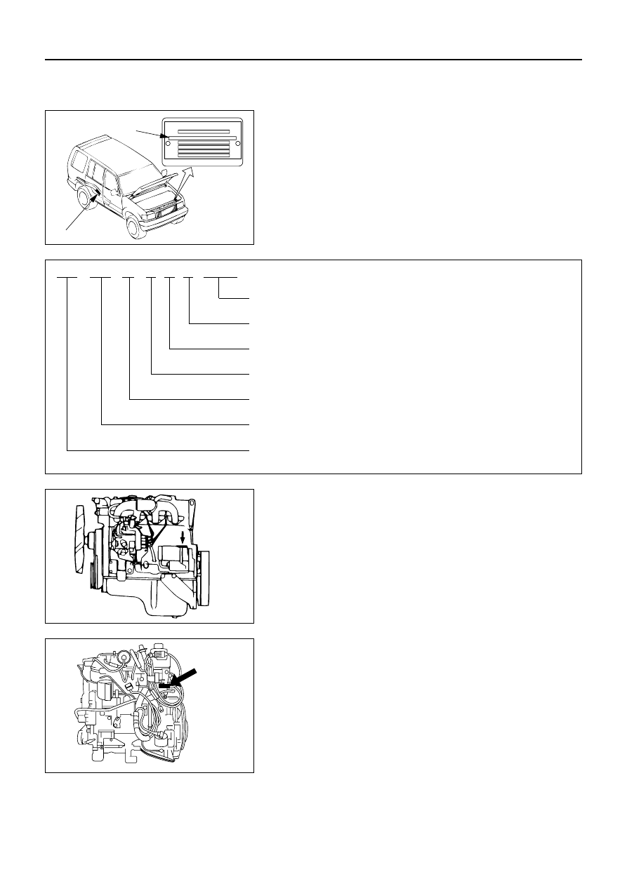
VEHICLE IDENTIFICATION NUMBER (VIN)

This is the legal identification of the vehicle.
It appears on the manufacturer’s Plate attached to the left
of the engine compartment front end. VIN number is also
stamped on the rear right side of the frame.

VIN

VIN

ISUZU MOTORS LTD.

JAC

UBS

25

G

Y

7

200001

Sequential Number

Plant Code

Model Year (Y: 2000)

Wheel Base (D: Short, G: Long)

Engine Type (25: 6VD1, 26: 6VE1, 69: 4JG2, 73: 4JX1)

Vehicle Model

World Manufacturer Identifier

ENGINE SERIAL NUMBER

The engine serial number is stamped on the left rear lower
area of the cylinder block above the starter.

4JG2

0A–6 GENERAL INFORMATION

IDENTIFICATION

905RY00014

4JX1

905RW014

GENERAL INFORMATION 0A–7

TRANSMISSION SERIAL NUMBER

Manual: Stamped on the left side of the transmission

intermediate plate.

Automatic: Stamped on the identification plate, located on

the left side of the transmission above the
mode switch.

96

0000 000

018

PART No.

SERIAL No.

SAL

HYDRAMATIC

STRASBOURG

MADE  IN FRANCE

G 20

272

FP

SERVICE PARTS IDENTIFICATION PLATE

The Vehicle Information Plate (Service Parts ID plate) is
provided on all vehicle models.
It is located on the center dash wall inside the engine
compartment. The plate lists the VIN (Vehicle Identification
Number), paint information and all production options and
special equipment on the vehicle when it was shipped
from the factory.

Service parts ID plate

ISUZU MOTORS L T D. JAPAN

V.I.N.
M.D.
ENGINE
GRADE

TRANS.
TIRE

BODY TYPE

B. COLOR/TRIM

OPTION

6VE1

and

6VD1

905RY00013

905RW015

905RW018

905RW007

0A–8 GENERAL INFORMATION

LIFTING INSTRUCTIONS

CAUTION:

If a lifting device other than the original jack
is used, it is most important that the device
be applied only to the correct lifting points.
Raising the vehicle from any other point
may result in serious damage.

When jacking or lifting a vehicle at the
frame side rail or other prescribed lift
points, be certain that lift pads do not
contact the catalytic converter, brake 
pipes or cables, or fuel lines. Such contact
may result in damage or unsatisfactory
vehicle performance.

LIFTING POINTS AND SUPPORTABLE POINT LOCATIONS

Long wheel Base Model

Short Wheel Base Model

Lifting point

Supportable point

GENERAL INFORMATION 0A–9

LIFTING POINT; FRONT

When using floor jack, lift on the center of the skid plate.

SUPPORTABLE POINT; FRONT

Position the chassis stands at the bottom of the frame
sidemember, backward of front wheel.

LIFTING POINT; REAR

Position the floor jack at the center of the rear axle case
when lifting the vehicle.

SUPPORTABLE POINT; REAR

Position the chassis stands at the bottom of the frame
sidemember, just behind of the trailing link bracket.

SUPPORTABLE POINT; REAR

Position the chassis stands at the bottom of the rear axle
case.


Content   ..  1  2  3   ..