Isuzu N-Series. Manual - part 275
 

  Index      Isuzu     Isuzu N-Series - service repair manual


Search            


Content   ..  273  274  275  276   ..


Isuzu N-Series. Manual - part 275


5A4-74 ABS/ASR

Speed Sensor (Front)

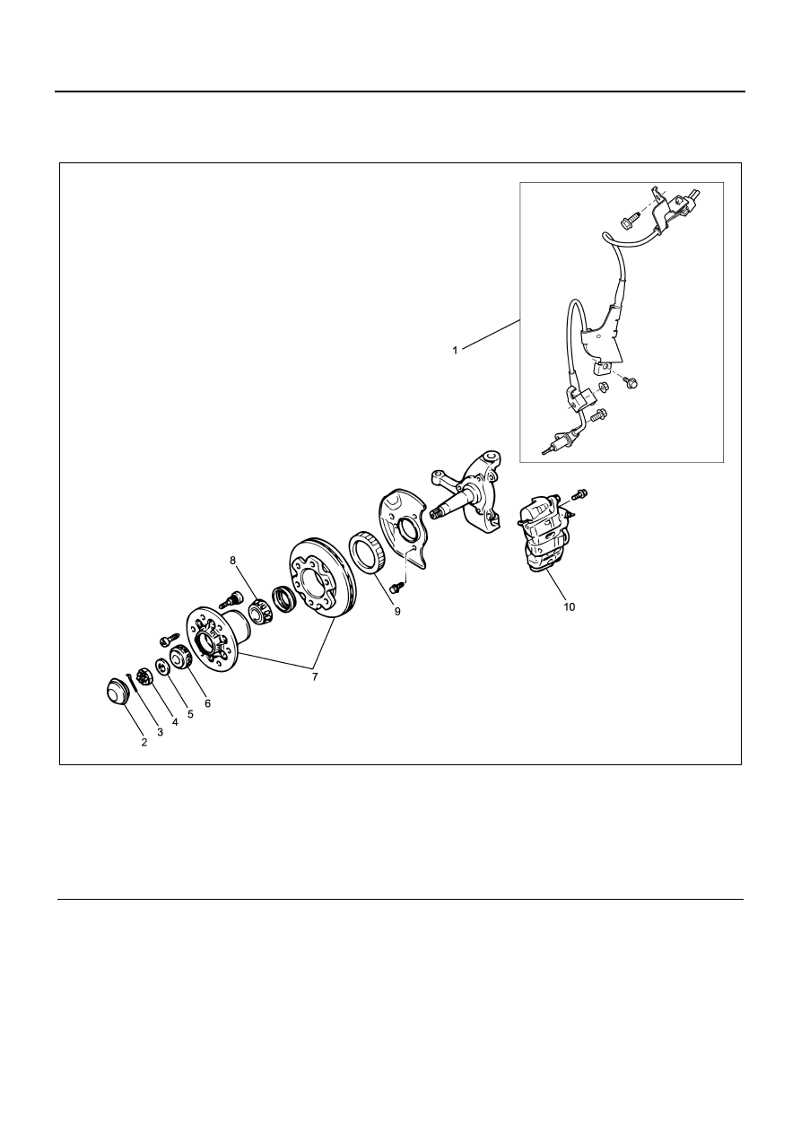
Components

Legend

1. Speed sensor (model with rigid suspension)
2. Hub cap
3. Cotter pin
4. Hub nut
5. Thrust washer

6. Outer bearing
7. Hub & rotor assembly
8. Inner bearing
9. Sensor rotor

10. Disc caliper assembly

Removal

1. Harness connector

• Disconnect the harness connector.

2. Harness fixing bolt

• Remove the harness fixing bolt.

3. Sensor fixing bolt

• Remove the sensor fixing bolt.

4. Speed sensor (front)

Installation

CAUTION:

• Do not let the speed sensor body contact with the

sensor rotor during hub assembly. Otherwise the
parts will be damaged.

• The speed sensor body has a built-in magnet. Be

careful not to allow metallic materials attached to it.

N5A2048E

ABS/ASR 5A4-75

• Remove the speed sensor before removing the

hub & rotor assembly or the hub & drum assembly.

• Remove the speed sensor before hammering to re-

move the knuckle etc.

• Use the harness line as a reference to avoid the

harness from twisting, when installing the sensor
harness.

• To install the sensor, press-fit the sensor until the

sensor flange contacts closely with the installing
surface by your hand, and then tighten with the
bolt.

1. Speed sensor (front)

• Install the speed sensor.

2. Sensor fixing bolt

• Install the sensor fixing bolt.

Tighten:

Bolt to 22 N

⋅m (2.2 kg⋅m / 16.2 lb⋅ft)

3. Harness fixing bolt

• Install the harness fixing bolt.

Frame side

Tighten:

Bolt to 22 N

⋅m (2.2 kg⋅m / 16.2 lb⋅ft)

Tighten together with the dust cover
(model with dram brake)

Tighten:

Bolt to 15 N

⋅m (1.5 kg⋅m / 11.1 lb⋅ft)

Tighten together with the brake support
(model with rigid disc brake)

Tighten:

Bolt to 45 N

⋅m (4.6 kg⋅m / 33.2 lb⋅ft)

4. Harness connector

• Connect the harness connector.

Inspection

This section explores inspection procedures as the ref-
erence to perform “Diagnostics with symptom” and “Di-
agnosis with illumination pattern”.

FL Wheel Speed Sensor Output Check Procedure
Check flow C-1-1

Without Tech 2

With Tech 2

Speed sensor output check

Check flow C-1-1 — C-1-4

Check flow TC-1

Step

Action

Value

YES

NO

1

1. Turn the starter switch OFF.
2. Disconnect the EHCU connector.
3. Jack-up the vehicle to lift the front wheels

off the floor.

4. Measure the AC voltage between the J-

177 connector terminals 32 and 33 while
turning the FL wheel half turn/sec.

Is the value within specified value?

200mV or 

more

Go to Step5

Go to Step2

2

1. Disconnect the FL sensor connector J-

75.

2. Measure the resistance between the J-75

connector terminals 1 and 2 (sensor
side).

Is the value within specified value?

1 — 2k

Ω

Go to Step4

Go to Step3

3

Replace the FL sensor.

Is this step completed?

—

Go to Step5

—

4

Repair the circuit for open/short circuit, and
the connector for improper connection
between the connector of EHCU and the sen-
sor connector.

Is this step completed?

—

Go to Step5

—

5A4-76 ABS/ASR

FR Wheel Speed Sensor Output Check Procedure
Check flow C-1-2

Speed Sensor Output Check Procedure (With Tech 2)
Check flow TC-1

5

1. Install all the components, and check that

those are installed properly.

2. Clear the DTC.

Is this step completed?

—

Go to “Diagnostic 

basic flow”.

Go to Step5

Step

Action

Value

YES

NO

1

1. Turn the starter switch OFF.
2. Disconnect the EHCU connector.
3. Jack-up the vehicle to lift the front wheels

off the floor.

4. Measure the AC voltage between the

J177 connector terminals 10 and 11 while
turning the FR wheel half turn/sec.

Is the value within specified value?

200mV or 

more

Go to Step5

Go to Step2

2

1. Disconnect the FR sensor connector J-

74.

2. Measure the resistance between the J-74

connector terminals 1 and 2 (sensor
side).

Is the value within specified value?

1 — 2k

Ω

Go to Step4

Go to Step3

3

Replace the FR sensor.

Is this step completed?

—

Go to Step5

—

4

Repair the circuit for open/short circuit, and
the connector for improper connection
between the connector of EHCU and the sen-
sor connector.

Is this step completed?

—

Go to Step5

—

5

1. Install all the components, and check that

those are installed properly.

2. Clear the DTC.

Is this step completed?

—

Go to “Diagnostic 

basic flow”.

Go to Step5

Step

Action

Value

YES

NO

1

1. Connect the Tech 2.
2. Check each sensor lowest speed from

the “Wheel sensor”.

 Is the sensor speed 4km/h (2mph) or more?

—

Go to Step2

Go to Step6

2

 Check the suspicious sensor circuit for open
circuit. (Check with shaking the wire and the
connector.)

 Is the sensor circuit connection normal?

—

Replace the 

speed sensor.Go 

to Step3

Repair.Go to 

Step3

Step

Action

Value

YES

NO

ABS/ASR 5A4-77

Used for checking the front speed sensor, or the rear
speed sensor when no DTC is set.

CAUTION:

On the vehicle that the rear tires have smaller diameter,
the rear wheel speed may be indicated a little higher
than the front wheel speed. Check the speed after driv-
ing a while at a constant speed.

3

Check each sensor lowest speed from the
“Wheel sensor”.

Is the sensor speed 4km/h (2mph) or more?

—

Go to Step4

Go to Step6

4

Check the sensor rotor.

Is the sensor rotor normal?

—

Go to Step5

Replace the sen-

sor rotor.Go to 

Step5

5

Check each sensor lowest speed from the
“Wheel sensor”.

Is the sensor speed 4km/h (2mph) or more?

—

Repair the circuit 

or circuit between 

the EHCU and the 

speed sensor. Go 

to Step6

Go to Step6

6

Install all the components, and check that
those are installed properly.

Is this step completed?

—

Repeat “Diagnos-

tic basic flow”.

Go to Step6

Step

Action

Value

YES

NO


Content   ..  273  274  275  276   ..