Isuzu engine 4j series. Manual - part 79
 

  Index      Isuzu     Isuzu engine 4j series - service manual


Search            


Content   ..  77  78  79  80   ..


Isuzu engine 4j series. Manual - part 79


6C - 60  ENGINE FUEL

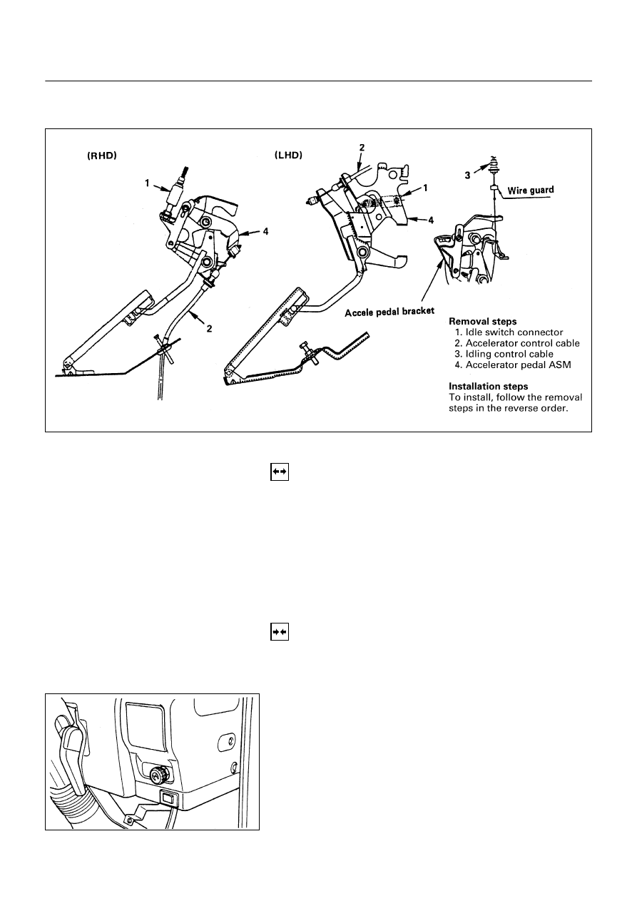
ACCELERATOR PEDAL

REMOVAL

1. Idle Switch Connector

2. Accelerator Control Cable

•

Remove control cable from Accelerator pedal bracket.

3. Idling Control Cable

•

Remove control cable from accelerator pedal bracket.

4. Accelerator Pedal Assembly

•

Remove accelerator pedal assembly from brake pedal
bracket.

INSTALLATION

4. Accelerator Pedal Assembly

•

Apply the sliding section with grease, and install it to
the brake pedal bracket.

3. Idling Control Cable

•

Install the cable to the lever of the accelerator pedal
bracket.

2. Accelerator Control Cable

•

After confirming that the idling control knob is fully
turned to the left, install the accelerator control cable.

1. Idle Switch Connector

6C-59-1.tif

6C-59-2.tif

ENGINE FUEL  6C - 61

Adjustment of the press-down amount of
the accelerator pedal

•

After installing each cable, give a full stroke to the
accelerator pedal while pushing the accelerator pedal
pad by hand.

•

Adjust the stopper bolt so that the clearance between
the pedal pad stopper bolt and the back of the pad
becomes 0 ~ 2 mm (0 ~0.079 in.), and tighten the lock
nut to the specified torque.

N∙m (Kg∙m/lb∙ft)


7.4 (0.75/65)


•

Check to see if the accelerator pedal play is in the
range of 5 ~ 10 mm (0.2 ~ 0.4 in.) above the pedal
pad.

•

Press down on the accelerator pedal fully, and check
to see if the engine rotates at the maximum speed with
the linkage in the smooth operation.

•

In the operating range of the accelerator pedal, check
to see if the accelerator pedal and the injection pump
lever return without fail to their original positions
respectively.

6C-60-1.tif

6C-60-2.tif

6C - 62  ENGINE FUEL

IDLING CONTROL CABLE

REMOVAL

1. Idling Control Knob

•

Loosen the idling control knob screw and remove the
knob from cable.

2. Idling Control Cable Nut

3. Wave Washer

4. Idling Control Cable

•

Remove control cable from accelerator pedal bracket.

INSTALLATION

4. Idling Control Cable.

•

Install Control Cable to Accelerator pedal bracket.

3. Wave Washer

2. Idling Control Cable Nut

•

Insert the idling control cable into the specified hole of
the instrument panel.

•

Install the washer to the cable, and tighten it with the
nut.

6C-61-1.tif

ENGINE FUEL  6C - 63

1. Idling Control Knob

•

Insert the idling control knob into the cable, and tighten
the screw.

Inspection:

•

With the idling control knob not in use, check to see if
the injection pump lever is at the idle position (with the
lever in contact with the stopper bolt).

•

With the idling control knob turned fully to the right,
check to see if the engine idles up to 1,500 rpm or
more.


Content   ..  77  78  79  80   ..