Isuzu engine 4j series. Manual - part 52
 

  Index      Isuzu     Isuzu engine 4j series - service manual


Search            


Content   ..  50  51  52  53   ..


Isuzu engine 4j series. Manual - part 52


6A1 – 76  4JB1/4JB1T/4JB1TC/4JG2 - ENGINE

CRANKSHAFT REAR OIL SEAL (Gear & Belt Drive Type)

REMOVAL

Preparation:

•

Disconnect battery ground cable

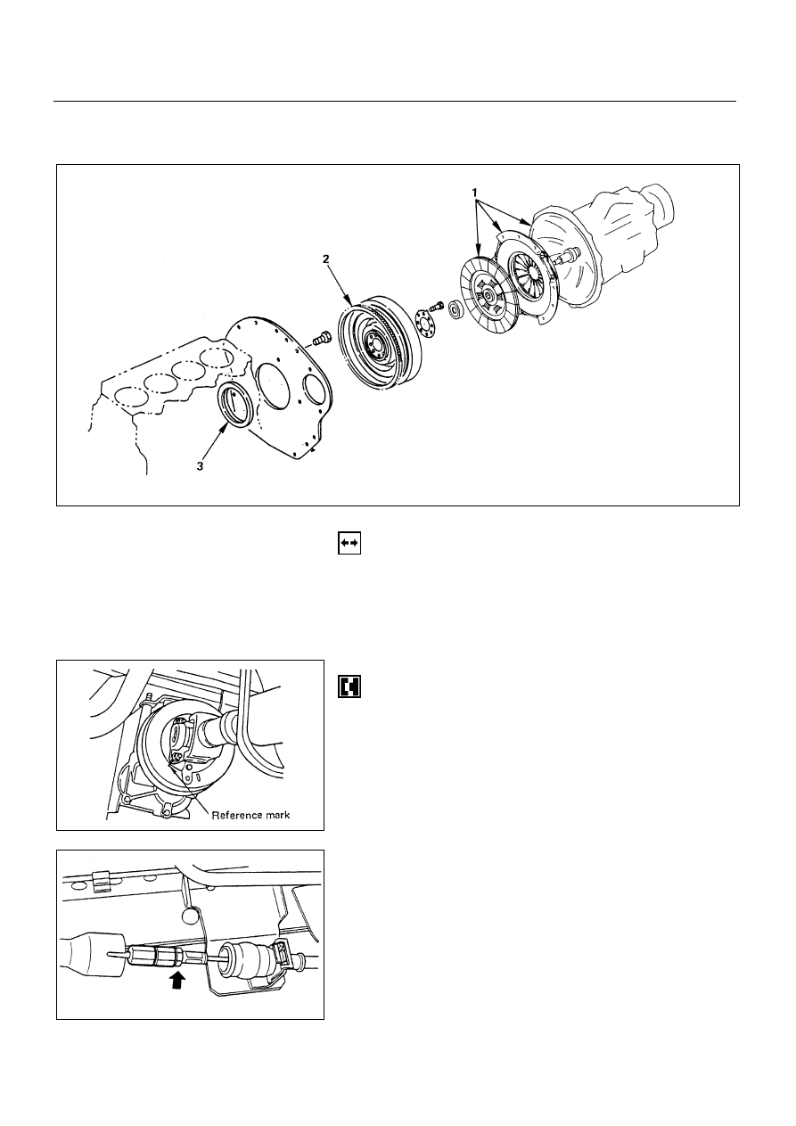
1. Transmission and Clutch Assembly

•

Raise vehicle and support with suitable safely.

1) Transmission

!

Transmission

•

Reference mark the flange yoke to the parking brake
drum.

•

Disconnect the propeller shaft at flange yoke.

•

Put aside the propeller shaft and tie it to the frame so
that it does not interface with servicing work.

"

Parking Brake Cable

•

Move the joint cover.

•

Disconnect the joint bolt.

•

Remove the clip then disconnect the cable from the
bracket.

6A1-76-1.tif

6A1-76-2.tif

6A1-76-3.tif

Removal steps

1.  Transmission and clutch Assembly
2. Flywheel
3.  Rear oil seal

Installation steps

To install, follow the removal steps in the
reverse order.

4JB1/4JB1T/4JB1TC/4JG2 – ENGINE  6A1 – 77

#

Wiring Connector

•

Disconnect the wiring connectors from the car speed
sensor, the neutral switch and the back-up light switch.

$

Shift Cable and Select Cable

•

Disconnect the shift cable and select cable on the
transmission side.

%

Clutch Slave Cylinder

•

Remove the clutch pipe fixing clips and the clip
bracket (Right hand drive models only).

•

Remove the slave cylinder assembly with the flexible
hose attached, and then tie it to the frame so that it
does not interface with servicing work.

&

Exhaust Brake Assembly

'

Front Exhaust Pipe

6A1-77-1.tif

6A1-77-2.tif

6A1-77-3.tif

6A1-77-4.tif

6A1 – 78  4JB1/4JB1T/4JB1TC/4JG2 - ENGINE

(

Transmission Assembly

NOTE:

The exhaust pipe bracket, the gear control bracket
and the clips are sometimes installed in the wrong
position or direction confusedly. To prevent incorrect
installation of these parts, put a correct installation
mark on them.
•

Support the transmission with mission jack.

CAUTION:

To prevent the falling of the transmission, tie it firmly
to the jack with a chain or belt.

Do not allow transmission to hang unsupported from
clutch. Damage to the clutch assembly will result.

•

Remove the nuts of the transmission mounting bracket
on the crossmember side.

•

Engine and transmission angles may need to be
adjusted for removal.

•

Hold the rear section of the engine by the jack or hoist.

CAUTION:

When lifting the engine by the jack, use wood blockes
to prevent any possible damage to the oil pan.
•

Remove transmission fastening bolts.

•

Pull out the transmission assembly rearward.

)

Mounting Bracket

6A1-78-1.tif

4JB1/4JB1T/4JB1TC/4JG2 – ENGINE  6A1 – 79

2) Clutch
•

Raise vehicle and support with suitable safety stands.

CAUTION:

Do not let clutch fluid remain on a painted surface,
Wash it off immediately.

!

Pressure Plate Assembly

"

Driven Plate Assembly

•

Use the pilot aligner to prevent the driven plate
assembly from falling free.
Pilot Aligner: 5-5825-3001-0

•

Mark the flywheel and pressure plate lug for alignment
when installing.

•

Loosen the pressure plate assembly fixing bolts.

2. Flywheel

3. Rear Oil Seal

•

With the oil seal pushed in deep, install the special tool
as shown in the illustration to remove the oil seal.

•

Rear oil seal Remove: 5-8840-2360-0

NOTE:

Take care not to damage the crankshaft or oil seal
retainer when removing oil seal.

6A1-79-1.tif

6A1-79-2.tif


Content   ..  50  51  52  53   ..