Isuzu engine 4j series. Manual - part 44
 

  Index      Isuzu     Isuzu engine 4j series - service manual


Search            


Content   ..  42  43  44  45   ..


Isuzu engine 4j series. Manual - part 44


6A1 – 44  4JB1/4JB1T/4JB1TC/4JG2 - ENGINE

Valve Clearance Adjustment

Above works refer to “ROCKER ARM SHAFT
ASSEMBLY” Section in this manual.

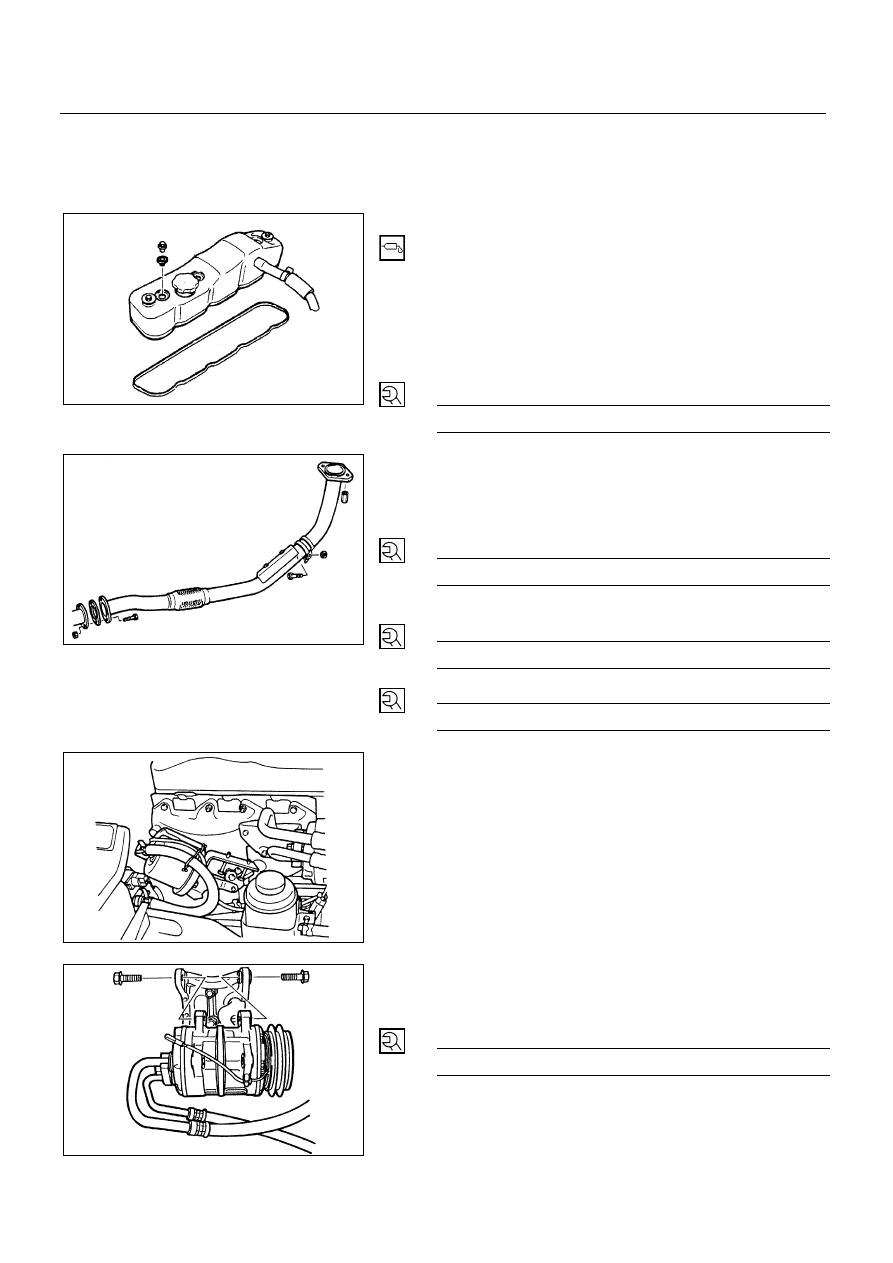
16. Cylinder Head Cover

•

Apply engine oil to the rocker arms and the valve
spring.

•

Install the cylinder head cover gasket to the cylinder
head cover.

•

The gasket must be perfectly smooth with no loose
areas.

•

Tighten the cylinder head cover nuts to the specified
torque in the numerical order shown in the illustration.

Cylinder Head Cover Torque

N∙m (kg∙m/lb∙in)


13 (1.3/113)


15. By-Pass Hose

14. Front Exhaust Pipe

•

Install the pipe to manifold and tighten bolts and nuts
to the specified torque.

W/Exhaust Brake Manifold Nut Torque

N∙m (kg∙m/lb∙ft)


37 (3.8/27)


WO/Exhaust Brake
Manifold Nut Torque

N∙m (kg∙m/lb∙ft)


40 (4.1/30)


Pipe Stay Bolts Torque

N∙m (kg∙m/lb∙ft)


40 (4.1/30)


13. Vacuum Actuator Hose (Exhaust Brake Model)

•

Install the vacuum hose to the vacuum actuator.

12. A/C Compressor Assembly (A/C Model)

•

Install the A/C compressor fixing bolts and tighten
bolts to the specified torque.

Compressor Bolts Torque

N∙m (kg∙m/lb∙ft)


37 (3.8/27)


6A1-44-1.tif

6A1-44-2.tif

6A1-44-3.tif

6A1-44-4.tif

4JB1/4JB1T/4JB1TC/4JG2 – ENGINE  6A1 – 45

11. Oil Cooler Water Pipe (Oil Cooler Model)

•

Install the water pipe bolt and tighten bolt to the
specified torque.

Water Pipe Nut Torque

N∙m (kg∙m/lb∙ft)


19 (1.9/14)


Pipe Bracket Bolt Torque

N∙m (kg∙m/lb∙ft)


40 (4.1/30)


10. Oil Level Gauge Guide Tube

•

Install the guide tube bolt and tighten bolt to the
specified torque.

Guide Tube Bolt Torque

N∙m(kg∙m/lb∙ft)


19 (1.9/14)


9. Glow Plug Harness

8. PCV Hose

7. Leak Off Pipe

•

Mount using a new copper washer.

6. Injection Pipe

•

Install the flare nut to injection pump side.

•

Install the flare nut to injection nozzle side.

•

Tighten the flare nut to the specified torque.

Flare Nut torque

N∙m (kg∙m/lb∙ft)


29 (3.0/22)


•

Fit pipe clip in specified torque.

6A1-45-1.tif

6A1-45-2.tif

6A1-45-3.tif

6A1-45-4.tif

6A1 – 46  4JB1/4JB1T/4JB1TC/4JG2 - ENGINE

5. Air Intake Duct

4. Engine Harness

•

Connect the thermo-sensor harness and thermo-meter
unit harness.

3. A/C Compressor Drive Belt (A/C Model)

Check drive belts for wear or damage, and replace with
new ones as necessary. Check belts for tension, and
adjust as necessary.
•

Check drive belts tension.

•

Push the middle of belts with a force of 10kg and
check each bolt for deflection.

•

Standard deflection

mm (in)

Initial tension

AC generator & fan pulley drive belt

A/C compressor drive belt

P/S pump drive belt

8 - 12 (0.31 - 0.47)

TENSION ADJUSTMENT

P/S oil pump and A/C compressor pulley belt
•

With P/S pump lock bolt loose, adjust belt tension with
adjust belt.

Cooling fan pulley belt
•

With AC Generator mounting and lock bolts loose,
adjust belt tension with adjuster's adjust bolt.

Torque Standard

N∙m (kg∙m/lb∙ft)

AC generator fixing bolt

40 (4.1/30)

Adjust plate fixing bolt

19 (1.9/14)

Adjust plate lock bolt

19 (1.9/14)

6A1-46-1.tif

6A1-46-2.tif

6A1-46-3.tif

6A1-46-4.tif

4JB1/4JB1T/4JB1TC/4JG2 – ENGINE  6A1 – 47

2. Heater Hose

•

Connect the heater hose them tighten clip securely.

1. Radiator Hose Upper

•

Connect the radiator hose them tighten clip securely.

•

Pour coolant

•

Connect battery ground cable.

•

Start the engine and check coolant leakage.


Content   ..  42  43  44  45   ..