Isuzu Trooper (2000 year). Manual - part 445
8A–20
LIGHTING SYSTEM
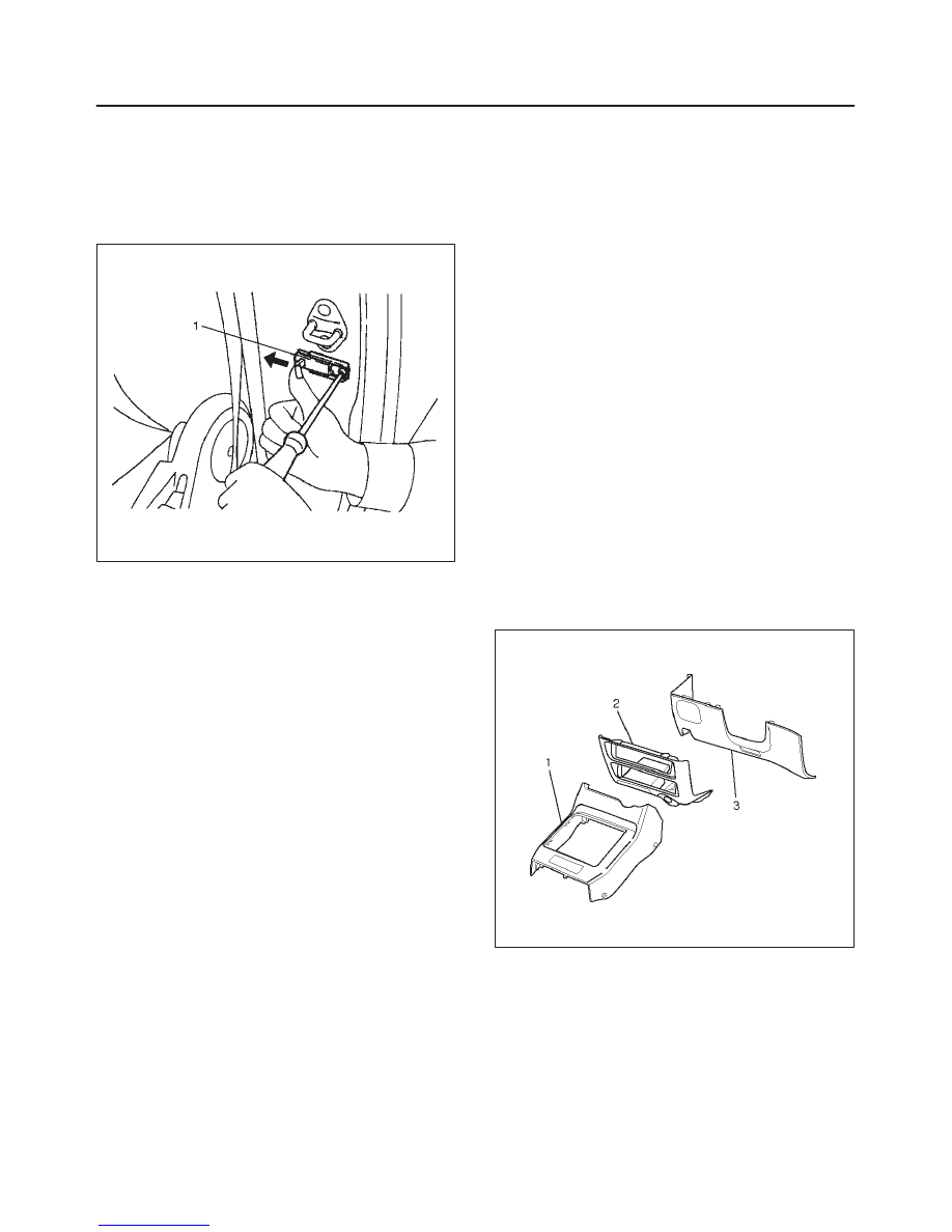
Door Switch
Removal
1. Disconnect the battery ground cable.
2. Remove the screw and disconnect the connector to
remove the door switch(1).
825RS043
Installation
To install, follow the removal steps in the reverse order.
Rear Defogger Switch
Removal
1. Disconnect the battery ground cable.
2. Remove the front console assembly(1).
Refer to the Instrument Panel Assembly in Body
Structure section.
3. Remove the lower cluster assembly(2).
Refer to the Instrument Panel Assembly in Body
Structure section.
4. Remove the instrument panel driver lower cover
assembly(3).
Refer to the Instrument Panel Assembly in Body
Structure section.
821RW024
5. Remove the instrument panel cluster assembly(4).
Refer to the Instrument Panel Assembly in Body
Structure section.
6. Disconnect the connector and push the lock from the
back side of the instrument panel cluster assembly to
remove the rear defogger switch(5).