Isuzu Trooper (2000 year). Manual - part 437
7C–12
CLUTCH
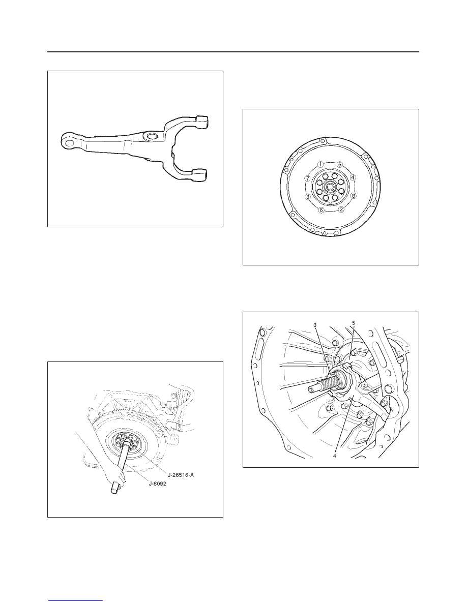
Shift Fork
201RS014
1. Visually check the surfaces of the shift fork making
contact with the release bearing for excessive wear
and damage.
2. Remove any minor stepping or abrasion from shift
fork with an oil stone.
3. Replace any exhibiting excessive wear or damage.
Installation
To install, follow the removal steps in the reverse order,
noting the following points:
1. Install flywheel assembly and crankshaft bearing, use
the installer J-26516-A and driver handle J-8092 to
install the crankshaft bearing then clean and lubricate
with grease.
015RS046
2. Install new flywheel fixing bolts in the order illustrated
and tighten them to the specified torque.
Torque: 54 N·m (40 lb ft)
NOTE: Do not reuse the bolt and do not apply oil or thread
lock to the bolt.
015RS047
3. Install the front cover (5) to the transmission case.
4. Tighten three fulcrum bridge bolts to the specified
torque.
Torque: 16.5 N·m (12 lb ft)
220RW088
5. Apply molybednum disulfide type grease to the pin
hole inner circumferences and thrust surfaces.
6. Attach the shift fork to the front cover and insert the
pin from below of the front cover.