Isuzu Trooper (2000 year). Manual - part 411
7A1–58 TRANSMISSION CONTROL SYSTEM (4L30–E)
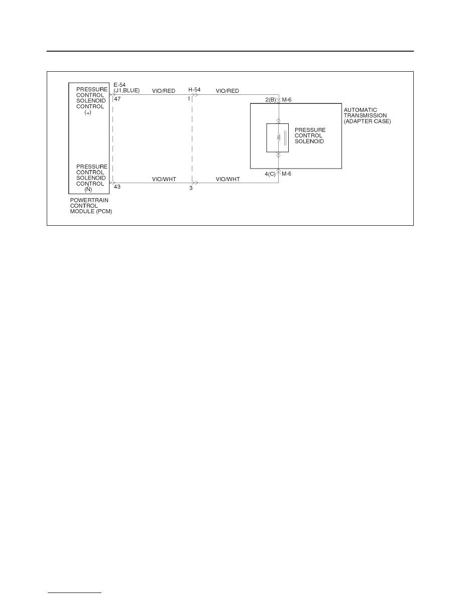
DTC P0748 Pressure Control Solenoid (PCS) (Force Motor) Circuit Electrical
D07RY00013
Circuit Description
The PCS is a PCM–controlled device used to regulate
transmission line pressure. The PCM compares TPS
voltage, engine rpm, and other inputs to determine the
line pressure appropriate for a given load. The PCM will
regulate the pressure by applying a varying amperage to
the PCS. The applied amperage can vary from 0.1 to 1
amp, and is monitored by the PCM.
This DTC detects a continuous open or short to ground in
the PCS circuit or the PCS. This is a type “C” DTC.
Conditions For Setting The DTC
D
Battery voltage is between 10 and 16 volts.
D
The PCM detects that the different between
commanded and actual current is 200 milliampere
(mA) for over 1 second.
D
Engine speed is greater than 300 rpm.
Action Taken When the DTC Sets
D
The PCM will not illuminate the Malfunction Indicator
Lamp (MIL).
D
Maximum line pressure.
D
The PCM will illuminate the CHECK TRANS Lamp.
D
Turn force motor OFF (Durability).
Conditions For Clearing The DTC/CHECK
TRANS Lamp
D
The PCM will turn “off” the CHECK TRANS Lamp
after three consecutive ignition cycles without a
failure reported.
D
The DTC can be cleared from PCM history by using a
scan tool.
D
The DTC will be cleared from memory when the
vehicle has achieved 40 warmup cycles without a
failure reported.
D
The PCM will cancel the DTC default actions when
the fault no longer exists and the ignition is cycled “off”
long enough to power down the PCM.
Diagnostic Aids
D
Inspect the wiring for poor electrical connection at the
PCM and at the transmission 4–way connector. Look
for possible bent, backed out, deformed or damaged
terminals. Check for weak terminal tension as well.
Also check for a chafed wire that could short to bare
metal or other wiring. Inspect for a broken wire inside
the insulation.
D
When diagnosing for a possible intermittent short or
open condition, move the wiring harness while
observing test equipment for a change.
Test Description
The numbers below refer to the step numbers on the
diagnostic chart:
2. This test checks the ability of the PCM to command
the PCS.
3. This test checks the PCS and internal wiring harness
for incorrect resistance.