Isuzu Trooper (2000 year). Manual - part 363


  Index      Isuzu     Isuzu Trooper - service repair manual 2000 year


Search            


Content   ..  361  362  363  364   ..


Isuzu Trooper (2000 year). Manual - part 363


6E–581

TROOPER 6VE1 3.5L ENGINE DRIVEABILITY AND EMISSIONS

addition, the PCV valve can seal the common chamber
off in case of sudden high pressure in the crankcase.
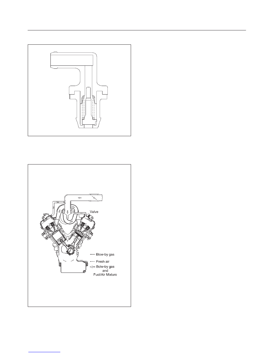
028RV002

While the engine is running, exhaust fuses and small
amounts of the fuel/air mixture escape past the piston
rings and enter the crankcase.  These gases are mixed
with clean air entering through a tube from the air intake
duct.

028RW002

During normal, part-throttle operation, the system is
designed to allow crankcase gases to flow through the
PCV valve into the throttle body to be consumed by
normal combustion.

A plugged valve or PCV hose may cause the following
conditions:

D

Rough idle.

D

Stalling of slow idle speed.

D

Oil leaks.

D

Sludge in the engine.

A leaking PCV hose would cause:

D

Rough idle.

D

Stalling.

D

High idle speed.

6E–582

TROOPER 6VE1 3.5L ENGINE DRIVEABILITY AND EMISSIONS

Special Tools

ILLUSTRATION

TOOL NO.

TOOL NAME

J 39200

High Impedance

Multimeter (Digital

Voltmeter – DVM)

(1) PCMCIA Card

(2) RS232 Loop Back

Connector

(3) SAE 16/19 Adapter

(4) DLC Cable

(5) TECH–2

J 34142-B

Unpowered Test Light

Connector Test Adapter

Kit J 35616-A/BT-8637

J 26792/BT-7220-1

Spark Tester

J 34730-E

Port Fuel Injection

Diagnostic Kit

ILLUSTRATION

TOOL NO.

TOOL NAME

J 23738-A

Vacuum Pump with

Gauge

BT-8515/8515V

Exhaust Back Pressure

Tester

J 39194-B

Heated Oxygen Sensor

Wrench

J 35689-A

Terminal Remover

J 28742-A

Weather Pack II

Terminal Remover

J 39021-90

Injector Switch Box

6E–583

TROOPER 6VE1 3.5L ENGINE DRIVEABILITY AND EMISSIONS

ILLUSTRATION

TOOL NO.

TOOL NAME

J 39021-65

Injector Test Light

J 41416

2

Ultrasonic Leak Detector

1. J 41416 Ultrasonic Leak Detector is a

microprocessor-based device used to detect leaks in
the enhanced evaporative emission control system.
The evaporative system is pressurized to 30 inches of
water using the J 41413 EVAP Pressure/Purge
Diagnostic System.  Small leaks in the EVAP system
will emit sound at a high frequency undetectable by a
human ear but detectable with the J 41416.  The
technician traces along the evaporative system and
can pinpoint leaks due to corroded lines, cracked
hoses, or a damaged EVAP component.  The
detector includes a high quality set of headphones to
block out surrounding shop noise and the LED
sensitivity meter allows a visual reference for locating
leaks in conjunction with the audio output heard
through the headphones.  Powered by (1) nine volt
battery.

6F–1

ENGINE EXHAUST

TROOPER

ENGINE

ENGINE EXHAUST

CONTENTS

General Description

6F–2

. . . . . . . . . . . . . . . . . . . . . 

Front Exhaust Pipe

6F–3

. . . . . . . . . . . . . . . . . . . . . . 

Front Exhaust Pipe and Associated Parts

6F–3

Removal

6F–3

. . . . . . . . . . . . . . . . . . . . . . . . . . . . . 

Installation

6F–3

. . . . . . . . . . . . . . . . . . . . . . . . . . . . 

Three Way Catalytic Converter LH

6F–4

. . . . . . . . . 

Removal

6F–4

. . . . . . . . . . . . . . . . . . . . . . . . . . . . . 

Installation

6F–4

. . . . . . . . . . . . . . . . . . . . . . . . . . . . 

Three Way Catalytic Converter RH

6F–5

. . . . . . . . 

Removal

6F–5

. . . . . . . . . . . . . . . . . . . . . . . . . . . . . 

Installation

6F–5

. . . . . . . . . . . . . . . . . . . . . . . . . . . . 

Exhaust Silencer

6F–6

. . . . . . . . . . . . . . . . . . . . . . . . 

Exhaust Silencer and Associated Parts

6F–6

. . . 

Removal

6F–6

. . . . . . . . . . . . . . . . . . . . . . . . . . . . . 

Installation

6F–6

. . . . . . . . . . . . . . . . . . . . . . . . . . . . 

Rear Exhaust pipe

6F–7

. . . . . . . . . . . . . . . . . . . . . . . 

Rear Exhaust pipe and Associated Parts

6F–7

Removal

6F–7

. . . . . . . . . . . . . . . . . . . . . . . . . . . . . 

Installation

6F–7

. . . . . . . . . . . . . . . . . . . . . . . . . . . . 

Main Data and Specifications

6F–8

. . . . . . . . . . . . . 


Content   ..  361  362  363  364   ..