Isuzu Trooper (2000 year). Manual - part 353
 

  Index      Isuzu     Isuzu Trooper - service repair manual 2000 year


Search            


Content   ..  351  352  353  354   ..


Isuzu Trooper (2000 year). Manual - part 353


6E–541

TROOPER 6VE1 3.5L ENGINE DRIVEABILITY AND EMISSIONS

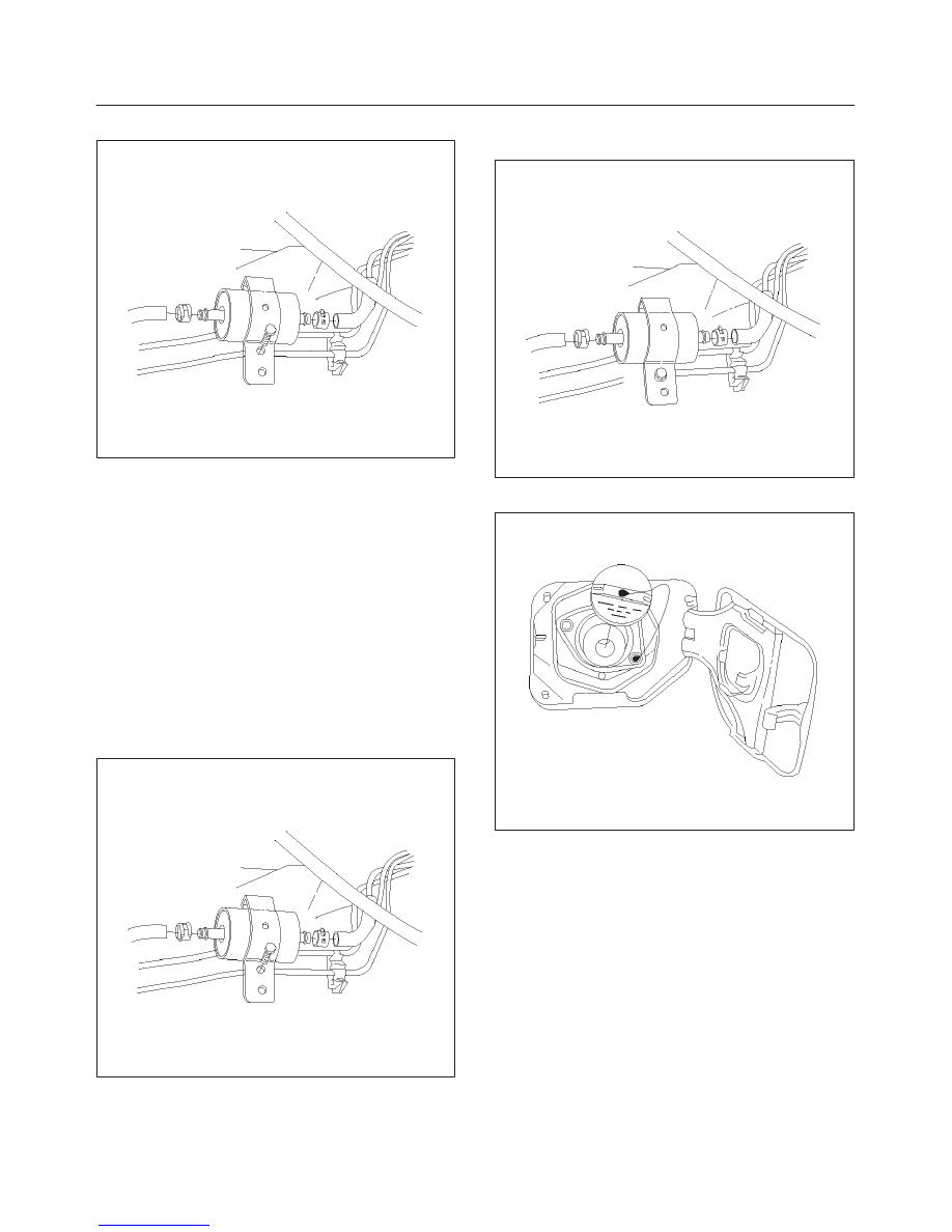
5. Remove the bolt on the fuel filter holder.

041RW007

6. Remove the fuel filter.

Inspection Procedure

1. Replace the fuel filter when the following occur:

D

Fuel leaks from the fuel filter body.

D

The fuel filter body is damaged.

D

The fuel filter is clogged with dirt or sediment.

Installation Procedure

1. Install the fuel filter in the correct direction.
2. Install the bolt on the fuel filter holder.

Tighten

D

Tighten the screws to 20 N·m (14 lb ft.).

041RW007

3. Connect the fuel line on the engine side.
4. Connect the fuel line on the fuel tank side.

041RW006

5. Install the fuel filler cap.

041RW005

6. Connect the negative battery cable.

6E–542

TROOPER 6VE1 3.5L ENGINE DRIVEABILITY AND EMISSIONS

Fuel Gauge Unit

Removal Procedure

1. Disconnect the negative battery cable.
2. Loosen the fuel filler cap.
3. Drain the fuel from the tank.

Tighten

D

Tighten the drain plug to 20 N·m (14 lb ft.).

TS22907

4. Disconnect the wiring connector from the fuel gauge

unit.

TS23771

5. Remove the fuel gauge unit retaining screws.
6. Remove the fuel gauge unit.

D

Cover or plug the fuel tank to prevent dust, dirt, or
debris from entering the tank.

TS22911

Installation Procedure

1. Install the fuel gauge unit.
2. Install the fuel gauge unit retaining screws.

TS22911

6E–543

TROOPER 6VE1 3.5L ENGINE DRIVEABILITY AND EMISSIONS

3. Connect the wiring connector to the fuel gauge unit.

TS23771

4. Fill the fuel tank with fuel.

D

Tighten the fuel filler cap.

D

Check for leaks at the fuel gauge unit gasket.

5. Connect the negative battery cable.

Fuel Injectors

Removal Procedure

NOTE: If the fuel injectors are leaking, the engine oil may
be contaminated with fuel.  Check the oil for signs of
contamination and change the oil and the filter if
necessary.

NOTE: Use care in removing the fuel injectors in order to
prevent damage to the fuel injector electrical connector
pins or the fuel injector nozzles.  The fuel injector is an
electrical component and should not be immersed in any
type of cleaner as this may damage the fuel injector.

IMPORTANT:

Fuel injectors are serviced as a complete

assembly only.

1. Disconnect the negative battery cable.
2. Remove the common chamber.  Refer to 

Common

Chamber in Engine Mechanical section.

3. Remove the fuel rail.  Refer to 

Fuel Rail section.

014RW164

4. Remove the injector retainer clip. 

055RW009

5. Remove the fuel injector assembly.
6. Remove the O-ring from the fuel injector.
7. Remove the O-ring backup from the fuel injector .

Inspection Procedure

1. Inspect the O-rings for cracks or leaks.
2. Replace worn or damaged O-rings.
3. Lubricate the new O-rings with engine oil before

installation.

6E–544

TROOPER 6VE1 3.5L ENGINE DRIVEABILITY AND EMISSIONS

Installation Procedure

1. Install the O-ring backup on the fuel injector.
2. Install the new O-ring on the fuel injector.
3. Install the fuel injector on the fuel rail.

055RW009

4. Use new fuel injector retainer clips to retain the fuel

injector to the fuel rail.

5. Coat the end of the fuel injector with gasoline.
6. Install the fuel rail.  Refer to 

Fuel Rail section.

014RW164

7. Install the common chamber.  Refer to 

Common

Chamber in Engine Mechanical section.

8. Install the engine cover.
9. Connect the negative battery cable.

Fuel Metering System

Fuel Pressure Relief Procedure

CAUTION: To reduce the risk of fire and personal
injury, there are necessary to relieve the fuel system
pressure filler and gauge unit before servicing the
fuel system components.

CAUTION: After  relieving the system pressure, a
small amount of fuel may be released when servicing
fuel lines or connections.  Reduce the chance of
personal injury by covering the fuel line fittings with
a shop towel before you disconnect the fittings.  The
towels will absorb any fuel that may leak out.  When
the disconnect is completed, place the towel in an
approved container.

1. Remove the fuel cap.
2. Remove the fuel pump relay from the underhood

relay box.  Refer to 

Fuel Pump Relay section.

TS23976R

3. Start the engine and allow it to stall.
4. Crank the engine for 30 seconds.
5. Disconnect the negative battery cable.


Content   ..  351  352  353  354   ..