Isuzu Trooper (2000 year). Manual - part 135


  Index      Isuzu     Isuzu Trooper - service repair manual 2000 year


Search            


Content   ..  133  134  135  136   ..


Isuzu Trooper (2000 year). Manual - part 135


TRANSFER CASE (STANDARD TYPE)

4D1–17

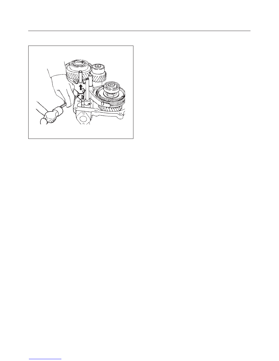
16. Engage the 2WD–4WD sleeve with the 4WD side and

install the spring pin.

262RW022

17. Install spring pin and bridge.
18. Install detent ball, spring and plug and tighten the plug

to the specified torque.

Torque: 25 N·m (18 lb ft)

4D1–18 TRANSFER CASE (STANDARD TYPE)

Transfer Case Assembly

Disassembled View

226RW132

Legend

(1) Transfer Case (with oil seal)
(2) Bearing Snap Ring
(3) Front Output Gear Assembly
(4) Ball Bearing
(5) Front Output Shaft
(6) Stopper Plate
(7) 2WD–4WD Clutch Hub and Assembly
(8) Block Ring
(9) Outside Ring

(10) Inside Ring

(11) Front Output Gear

(12) Needle Bearing
(13) Sub–Gear (anti–lash plate) (M/T)
(14) Belleville Spring (M/T)
(15) Spacer (M/T)
(16) Sub–Gear Snap Ring (M/T)
(17) Bearing Collar
(18) Ball Bearing
(19) Bearing Snap Ring
(20) Snap Ring
(21) Ball Bearing

(22) Counter Gear
(23) Sub–Gear (anti–lash plate)
(24) Belleville Spring
(25) Spacer
(26) Ball Bearing
(27) Snap Ring
(28) Counter Gear Assembly
(29) Bearing Snap Ring
(30) Input Shaft Assembly
(31) Input Shaft
(32) Ball Bearing
(33) Snap Ring
(34) Plate
(35) Ball
(36) Bearing Collar
(37) Needle Bearing
(38) Transfer Input Gear
(39) High–Low Clutch Hub and Sleeve Assembly
(40) Lock Nut
(41) Ball Bearing
(42) Bearing Snap Ring

TRANSFER CASE (STANDARD TYPE)

4D1–19

Disassembly

1. Remove bearing snap ring, use a pair of snap ring

pliers to remove the snap ring.

2. Remove ball bearing, use a bearing remover J–37217

and puller J–37487 to remove the ball bearing.

262RW016

3. Install the front companion flange temporarily.
4. Use the Companion flange holder J–8614–11 and

lock nut wrench J–37219 to remove the lock nut.

226RW130

5. Remove the front companion flange.
6. Remove snap ring.

7. Remove the input shaft assembly from the transfer

case.

265RW001

8. Remove high–low clutch hub and sleeve.
9. Remove transfer input gear, use the universal puller

to remove the high–low clutch hub and sleeve, and
transfer input gear.

226RS070

10. Remove needle bearing.

4D1–20 TRANSFER CASE (STANDARD TYPE)

11. Remove bearing collar.

226RS071

12. Remove ball.
13. Remove plate.
14. Remove ball bearing, use a bench press and the ball

bearing remover J–22912–01 to remove the ball
bearing.

265RS002

15. Remove input shaft.
16. Remove bearing snap ring.

17. Remove front output gear assembly, use a pair of

snap ring pliers to expand the bearing snap ring and
use a plastic hammer to tap the front output gear
assembly free.

262RS009

18. Remove bearing snap ring.
19. Remove ball bearing.
20. Remove bearing collar.
21. Remove sub–gear snap ring. (M/T)
22. Remove spacer. (M/T)
23. Remove belleville spring. (M/T)
24. Remove sub–gear (anti–lash plate). (M/T)
25. Remove front output gear.
26. Remove needle bearing, use a bench press and the

bearing remover J–22912–01 to remove the parts
above.

262RS010

27. Remove inside ring.
28. Remove outside ring.
29. Remove block ring.


Content   ..  133  134  135  136   ..