Isuzu Trooper (2000 year). Manual - part 25
HEATING, VENTILATION AND AIR CONDITIONING (HVAC) 1A–69
871RW002
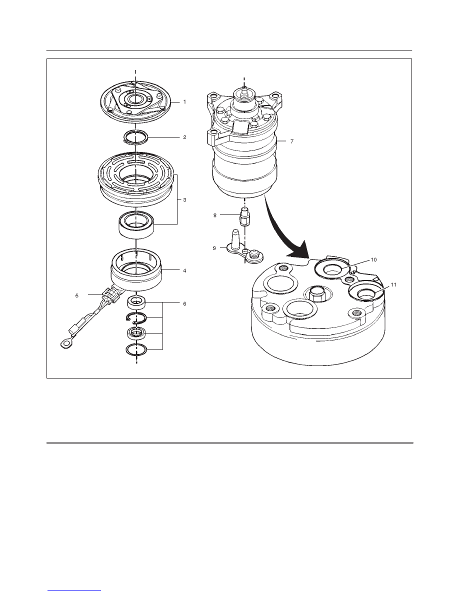
Legend
(1) Clutch Driver
(2) Rotor Bearing Retainer
(3) Pulley Rotor and Bearing Assembly
(4) Clutch Coil Assembly
(5) Connector
(6) Shaft Seal Parts
(7) Pump Assembly
(8) High Pressure Relief Valve
(9) Shipping Cap
(10) Special 134a Suction Port
(11) Special 134a Discharge Port
The operations described below are based on bench
overhaul with the compressor removed from the vehicle,
except as noted. They have been prepared in order of
accessibility of the components. When a compressor is
removed from the vehicle for servicing, the amount of
PAG lubricant remaining in the compressor should be
drained, measured and recorded. This PAG lubricant
should then be discarded and an equal amount of new
PAG lubricant added to the compressor.
The service compressor is shipped without PAG oil.
When service procedures require, use only Isuzu
approved PAG oil.