Isuzu Trooper (2000 year). Manual - part 22


  Index      Isuzu     Isuzu Trooper - service repair manual 2000 year


Search            


Content   ..  20  21  22  23   ..


Isuzu Trooper (2000 year). Manual - part 22


HEATING, VENTILATION AND AIR CONDITIONING (HVAC) 1A–57

Condenser Assembly

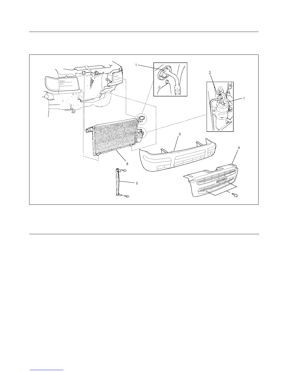
Condenser Assembly and Associated Parts

875RY00005

Legend

(1) Refrigerant Line
(2) Pressure Switch Connector
(3) Front Bumper Assembly

(4) Radiator Grille
(5) Engine Hood Front End Stay
(6) Condenser Assembly

Removal

1. Disconnect the battery ground cable.
2. Discharge and recover refrigerant.

D

Refer to Refrigerant Recovery in this section.

3. Remove radiator grille.
4. Remove front bumper assembly.

D

Refer to Bumpers in Body and Accessories section.

5. Remove engine hood front end stay.
6. Disconnect pressure switch connector.
7. Disconnect refrigerant line.

D

When removing the line connector, the connecting
part should immediately be plugged or capped to
prevent foreign matter from being mixed into the
line.

8. Remove condenser assembly.

D

Handle with care to prevent damaging the
condenser or radiator fin.

Installation

1. Install condenser assembly.

D

If installing a new condenser, be sure to add 30cc
(1.0 fl. oz.) of new compressor oil to a new one.

D

Tighten the condenser fixing bolts to the specified
torque.

Torque: 6 N

m (52 lb

in)

2. Connect refrigerant line.

D

Tighten the inlet line connector fixing bolt to the
specified torque.

Torque: 15 N

m (11 lb

ft)

D

Tighten the outlet line connector fixing bolt to the
specified torque.

Torque: 6 N

m (52 lb

in)

D

O-rings cannot be reused. Always replace with new
ones.

1A–58 HEATING, VENTILATION AND AIR CONDITIONING (HVAC)

D

Be sure to apply new compressor oil to the O-rings
when connecting the refrigerant line.

3. Connect pressure switch connector.

4. Install engine hood front end stay.
5. Install front bumper assembly.
6. Install radiator grille.

Receiver / Drier

Receiver / Drier and Associated Parts

875RY00004

Legend

(1) Pressure Switch Connector
(2) Refrigerant Line

(3) Receiver / Drier
(4) Radiator Grille
(5) Bracket Bolt

Removal

1. Disconnect the battery ground cable.
2. Discharge and recover refrigerant.

D

Refer to Refrigerant Recovery in this section.

3. Remove radiator grille.
4. Disconnect pressure switch connector.
5. Disconnect refrigerant line.

D

When removing the line connected part, the
connecting part should immediately be plugged or
capped to prevent foreign matter from being mixed
into the line.

6. Remove bracket bolt.
7. Remove receiver/drier.

D

Loosen the bolt, then, using care not to touch or
bend the refrigerant line, carefully pull out the
receiver/drier.

Installation

To install, follow the removal steps in the reverse order,
noting the following points:

1. If installing a new receiver/drier, be sure to add 30cc

(1.0 fl. oz.) of new compressor oil to a new one.

2. Put the receiver/drier in the bracket and connect with

the refrigerant line.  Check that no excessive force is
imposed on the line.  Fasten the bracket bolt to the
receiver/drier.

3. Tighten the refrigerant line to the specified torque.

Torque: 6 N

m (52 lb

in)

4. O-rings cannot be reused. Always replace with new

ones.

5. Be sure to apply new compressor oil to the O-rings

when connecting the refrigerant line.

HEATING, VENTILATION AND AIR CONDITIONING (HVAC) 1A–59

Pressure Switch

Pressure Switch and Associated Parts

875RY00006

Legend

(1) Pressure Switch Connector

(2) Pressure Switch
(3) Radiator Grille

Removal

1. Disconnect the battery ground cable.
2. Discharge and recover refrigerant.

D

Refer to “Refrigerant Recovery in this section.

3. Remove radiator grille.
4. Disconnect pressure switch connector.
5. Disconnect pressure switch.

D

When removing the switch connected part, the
connecting part should immediately be plugged or
capped to prevent foreign matter from being mixed
into the line.

Installation

To install, follow the removal steps in the reverse order,
noting the following point:

1. O-ring cannot be reused. Always replace with a new

one.

2. Be sure to apply new compressor oil to the O-ring

when connecting pressure switch.

3. Tighten the pressure switch to the specified torque.

Torque: 13 N

m (113 lb

in)

1A–60 HEATING, VENTILATION AND AIR CONDITIONING (HVAC)

Evaporator Assembly

Evaporator Assembly and Associated Parts

874RT002

Legend

(1) Resistor and Electronic Thermostat Connector
(2) Drain Hose
(3) Refrigerant Line
(4) Passenger Knee Bolster Reinforcement

Assembly

(5) Instrument Panel Passenger Lower Cover

Assembly

(6) Glove Box
(7) Front Console Assembly
(8) Lower Cluster Assembly
(9) Evaporator Assembly

Removal

1. Disconnect the battery ground cable.
2. Discharge and recover refrigerant.

D

Refer to Refrigerant Recovery in this section.

3. Remove front console assembly.
4. Remove lower cluster assembly.
5. Remove glove box.
6. Remove instrument panel passenger lower cover

assembly.

7. Remove passenger knee bolster reinforcement

assembly.

D

Refer to Instrument Panel Assembly in Body and
Accessories section.

8. Disconnect resistor (2) and electronic thermostat

connector (1).

874RY00009


Content   ..  20  21  22  23   ..