Isuzu KB P190. Manual - part 987
 

  Index      Isuzu     Isuzu KB P190 - service repair manual 2007 year


Search            


Content   ..  985  986  987  988   ..


Isuzu KB P190. Manual - part 987


Automatic Transmission – 4L60E – On-vehicle Servicing 

Page 7C4–35 

3.15  Spacer Plate, Check Balls, Filter Screens 

and 3 – 4 Accumulator 

Remove 

1 

Remove the control valve body, refer to 3.14 

Control Valve Body. 

2 

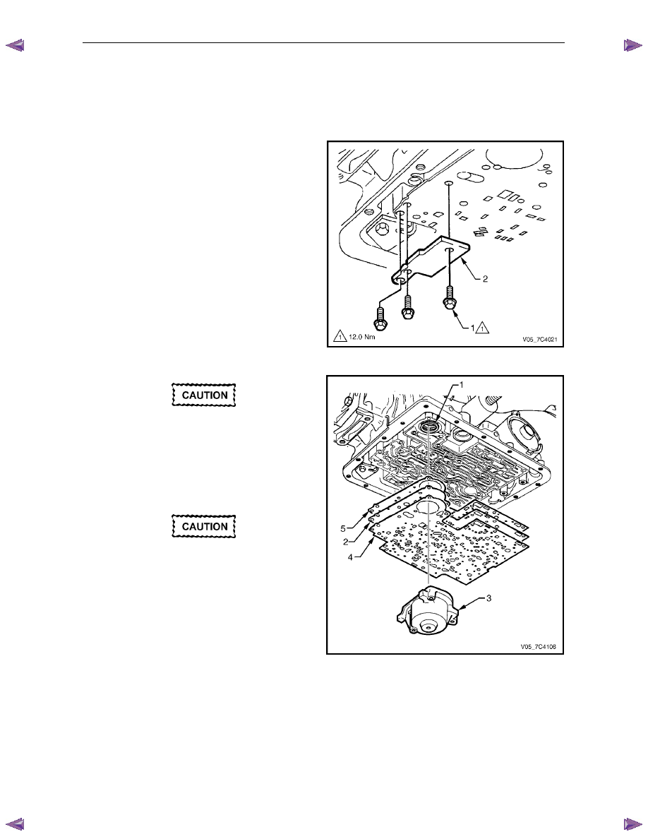
Remove the three attaching bolts (1) and the plate (2) 
supporting the spacer plate. 

Figure 7C4 – 47 


The 3 – 4 accumulator spring (1) may push 
the spacer plate away from transmission 
case when the 1 – 2 accumulator assembly is 
removed. 

3 

While supporting the spacer plate (2), carefully remove 
the 1 – 2 accumulator assembly (3), refer to  
3.12 

1 – 2 Accumulator Assembly. 


As the spacer plate and gaskets are lowered 
from the transmission, a check ball and the 
3 – 4 accumulator spring may drop. Do not 
lose the check ball and the spring. 

4 

Remove the two gaskets (4 and 5) and the spacer 
plate from the transmission case. 

Figure 7C4 – 48 

Automatic Transmission – 4L60E – On-vehicle Servicing 

Page 7C4–36 

5 

If not previously dropped, remove the spring (1). 
If required, use snap ring pliers to rotate and pull the 
3 – 4 accumulator piston (2) to remove it from the 
transmission case. Remove and discard the piston 
seal. 

Figure 7C4 – 49 

6 

Remove the check-ball (1) if not previously dropped. 
Remove the 3rd accumulator check ball assembly (2), 
the orifice cup plug (3) and the guide pins (A) from the 
transmission case. 


Figure 7C4 – 50 

Clean and Inspect 


To avoid personal injury, wear safety glasses 
and gloves when using compressed air and 
cleaning fluids. 

1 

Wash all components in a commercially available cleaning fluid and blow dry using compressed air. 

2 

Inspect the components for the following: 

• 

piston for porosity, 

• 

ring groove or pin hole damage, 

• 

spring for distortion or damage, 

• 

accumulator bore for wear or damage and 

• 

spacer plate, filter screens and check balls for damage. 

Automatic Transmission – 4L60E – On-vehicle Servicing 

Page 7C4–37 

Reinstall 

1 

Lubricate a new seal (1) with petroleum jelly and install 
it to the 3 – 4 accumulator piston (2). 

2 

Reinstall the piston onto the pin (3). The piston side 
with the three lugs (4) must face out of the bore. 

3 

Reinstall the 3 – 4 accumulator spring, use a small 
amount of petroleum jelly to hold it in place, as 
needed. 


Figure 7C4 – 51 


Ensure the guide pins are fully installed with 
no thread visible. Otherwise the spacer plate 
gasket could be caught in the thread during 
installation, resulting in incorrect alignment. 

4 

Reinstall the guide pins (A) at the correct locations in 
the transmission case. 

5 

Reinstall the check ball (1) in the transmission case 
using a small amount of petroleum jelly to hold it in 
place. 

6 

Reinstall the 3rd accumulator check ball assembly (2) 
and the orifice cup plug (3) in the transmission case. 

Figure 7C4 – 52 

Automatic Transmission – 4L60E – On-vehicle Servicing 

Page 7C4–38 

7 

If a new spacer plate (1) is installed, it is necessary to 
fit two filter screens (2 and 3) to the spacer plate. 

Figure 7C4 – 53 

N O T E  

When installing the spacer plate locate the 
gaskets as follows: 

•  The gasket (2) marked CA is fitted between 

the spacer plate and the transmission case. 

•  The gasket (3) marked VB is fitted between 

the spacer plate and the control valve body. 

8 

Reinstall the spacer plate (1) with the new 
gaskets (2 and 3) smeared with petroleum jelly. Hold 
the spacer plate in place until the 1 – 2 accumulator is 
reinstalled. 

9 

While supporting the spacer plate, carefully reinstall 
the 1 – 2 accumulator assembly (4), refer to  
3.12 

1 – 2 Accumulator Assembly. 

Figure 7C4 – 54 


Content   ..  985  986  987  988   ..