Isuzu KB P190. Manual - part 890
 

  Index      Isuzu     Isuzu KB P190 - service repair manual 2007 year


Search            


Content   ..  888  889  890  891   ..


Isuzu KB P190. Manual - part 890


Engine Management – V6 – Service Operations 

Page 6C1-3–36 


Remove 

1 

Turn the ignition switch off. 

2 

Raise the vehicle and support on safety stands, refer to 0A General Information for location of the jacking points.  

3 

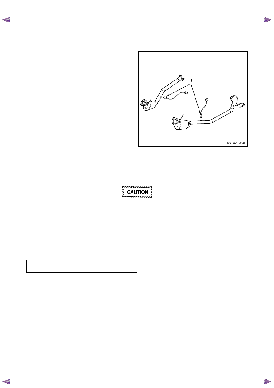
Unclip the HO2S wiring harness (1) from the 
transmission. 

4 

Depress the harness connector retaining clip (2) and 
separate the harness connectors. 

5 

Unscrew the HO2S (3) from the exhaust pipe and 
remove. 

6 

If required, test the HO2S, refer to the Test in this 
Section. 

Figure 6C1-3 – 46 

Reinstall 

Reinstallation of the heated oxygen sensor (HO2S) is the reverse of the removal procedure, noting the following: 


A special anti-seize compound is used on the 
HO2S threads. A new HO2S will already have 
the anti-seize compound applied to the 
threads. 

If a HO2S has been removed, but not replaced, 
then anti-seize compound must be applied to 
the threads prior to installation. 

1 

Coat the cleaned threads of the sensor with anti-seize compound. 

2 

Tighten the HO2S to the correct torque specification.  

Heated oxygen sensor 
torque specification .................................40.0 – 50.0 Nm 

3 

Road test the vehicle and check for correct operation, taking particular note that no exhaust leakage is evident. 

Engine Management – V6 – Service Operations 

Page 6C1-3–37 


Test 


Under no circumstances should battery 
voltage be applied to the heated oxygen 
sensor (HO2S) heater. 


To prevent component damage use connector 
test adaptor kit J 35616-A. 

Heater Resistance Check – Six Wire HO2S 

1 

Connect a digital ohmmeter using connector test 
adaptor kit J 35616-A to the HO2S. 

2 

Measure the resistance across terminals 3 and 4. 

3 

Compare the reading against the specification. 

HO2S heater resistance @ 20°C ................ 8.0 – 10.0 

Ω 

4 

If the resistance is not within specification, replace the 
HO2S.  

Figure 6C1-3 – 47 

Heater Resistance Check – Four Wire HO2S 

1 

Connect a digital ohmmeter using connector test 
adaptor kit J 35616-A to the HO2S. 

2 

Measure the resistance across terminals 1 and 2. 

3 

Compare the reading against the specification. 

HO2S heater resistance @ 20°C ................ 8.0 – 10.0 

Ω 

4 

If the resistance is not within specification, replace the 
HO2S.  

Figure 6C1-3 – 48 

Engine Management – V6 – Service Operations 

Page 6C1-3–38 


2.15 Ignition 

Coil 

Ignition Coils 

The replacement procedure for all ignition coils is the same except for the removal of the ignition coil on cylinder No's 1, 
3 and 4, it is necessary to remove the upper intake manifold assembly. 

Remove 

1 

Turn the ignition switch off. 

N O T E  

If the upper intake manifold has been removed, 
plug the lower manifold openings to prevent dirt 
and other contaminants from entering. 

2 

If required, remove the upper intake manifold assembly, refer to 6A1 Engine Mechanical – V6.  

3 

Using a flat-blade screwdriver, slide the connector 
retaining latch (1) in the direction of the arrow. 

4 

Remove the wiring harness connector from the ignition 
coil (2).  

Figure 6C1-3 – 49 


Clean the area around the ignition coil before 
removal to avoid debris from entering the 
engine. 

5 

Fully loosen the bolt (1) attaching the ignition coil (2) to 
the camshaft cover. 

N O T E  

The ignition coil bolts are captive. Do not attempt 
to remove the bolts from the ignition coil. 

6 

Remove the ignition coil by first, twisting the coil to 
release it, and then pulling the ignition coil upwards to 
remove it.  

Figure 6C1-3 – 50 

Engine Management – V6 – Service Operations 

Page 6C1-3–39 


Disassemble 


Do not use a sharp implement such as a knife 
to cut the ignition coil boot (1) from the 
ignition coil. Using a sharp implement may 
damage the ignition coil insulator (2). 

1 

Using your thumb, work the ignition coil boot off the 
ignition coil insulator. 

N O T E  

Take care the spring (3) does not become 
dislodged as the boot is removed. 

To aid removal of the boot, use a blunt 
instrument to lift the boot edge away from the 
coil insulator and spray a release agent between 
the boot and the coil insulator. 

2 

Remove the spring from the ignition coil insulator. 

Figure 6C1-3 – 51 

Reassemble 

1 

Position the spring (3) in the insulator recess, refer to Figure 6C1-3 – 51. 

2 

Lubricate the ignition coil insulator (1) with talcum 
powder. 

3 

Fit the ignition coil boot, ensuring it is fully seated at 
the top of the insulator. 

Figure 6C1-3 – 52 

Test 


Never probe the ignition coil with a 12 V tester 
as the ignition coil will be damaged.  

Due to the internal components of the ignition coil assembly, it is not possible to perform any primary and / or secondary 
resistance checks. For further information on the ignition coil operation, refer to 6C1-1 Engine Management – V6 – 
General Information. 


Content   ..  888  889  890  891   ..