Isuzu KB P190. Manual - part 829
 

  Index      Isuzu     Isuzu KB P190 - service repair manual 2007 year


Search            


Content   ..  827  828  829  830   ..


Isuzu KB P190. Manual - part 829


Engine Management – V6 – Diagnostics 

Page 6C1-2–38 


Step Action  Value(s) 

Yes 

No 

3 

1 

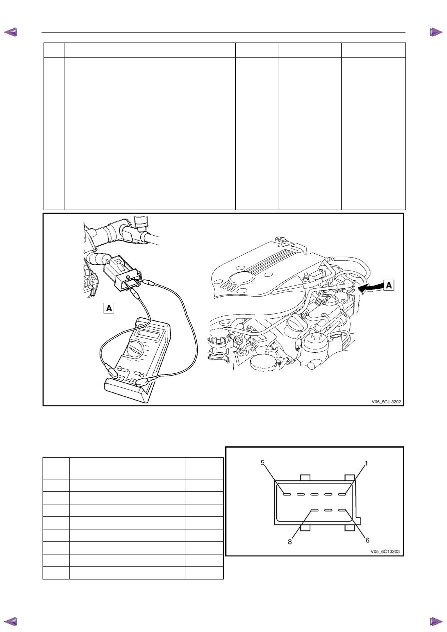
Disconnect the fuel injector harness connector, 
refer to 2.13 Fuel Rail Assembly, in 6C1-3 Engine 
Management – V6 – Service Operations. 

2 

Using a digital ohmmeter and connector test 
adaptor kit J 35616-A, measure the resistance of 
each fuel injector between the ignition voltage 
circuit and the fuel injector control circuit. Refer to 
8A Electrical - Body and Chassis for information 
on testing for continuity and to Figure 6C1-2 – 9 
and Figure 6C1-2 – 10 for the fuel injector 
harness connector. 

3 

Record each fuel injector value. 

4 

Subtract the lowest resistance value from the 
highest. 

Is the difference equal to, or less than, the specified 
value? 

3 

Ω 

Injectors OK 

Refer to Injector 
Coil Test – With 

Special Tool J39021

in this Section. 


Figure 6C1-2 – 9 

Fuel Injector Harness to Engine Harness Connector 

Pin Description 

Pin Function 

Circuit 

Number

1 

Ignition Voltage Circuit – Cyl. 1, 3, 5 

639 

2 

Ignition Voltage Circuit – Cyl. 2, 4, 6 

1039 

3 

Injector 1 Control Circuit 

1744 

4 

Injector 3 Control Circuit 

1746 

5 

Injector 5 Control Circuit 

845 

6 

Injector 2 Control Circuit 

1745 

7 

Injector 4 Control Circuit 

844 

8 

Injector 6 Control Circuit 

846 


Figure 6C1-2 – 10 

Engine Management – V6 – Diagnostics 

Page 6C1-2–39 


Injector Coil Test – With Special Tool J39021 

1 

Depressurise the fuel system, refer to 6C Fuel System – V6. 

2 

Turn the ignition OFF. 

N O T E  

After removing the upper intake manifold, plug 
the lower manifold opening to prevent dirt and 
other contaminants from entering. 

3 

Remove the upper intake manifold assembly, refer to 6A1 Engine Mechanical – V6. 

4 

Using Tech 2, observe the engine coolant temperature (ECT). If the ECT is 10 – 32

°C, refer to Engine Coolant 

Temperature Between 10 – 32

°C, or if the ECT is outside this range, refer to Engine Coolant Temperature Outside 

10 – 32

°C. 

Engine Coolant Temperature Between 10 – 32

°°°°C 

Step Action  Value(s) 

Yes 

No 

1 

1 

Set the amperage supply selector switch on the 
fuel injector tester (1), special tool J 39021 to the 
Coil Test 0.5 A position. Refer to  
Figure 6C1-2 – 11. 

2 

Connect the fuel injector tester leads (4 and 5) to 
B+ and ground.  

3 

Connect the digital multimeter (2) positive and 
negative lead to the fuel injector tester. Set the 
multimeter to read DC Voltage. 

4 

Connect the fuel injector tester, using fuel injector 
harness adapter, special tool J44602 to a fuel 
injector. 

5 

Press the Push to Start Test button on the fuel 
injector tester. 

6 

Observe and record the voltage reading on the 
digital multimeter. 

N O T E  

The voltage reading may rise during the 
test. Record the voltage reading after one 
second of the test. 

7 

Repeat steps 4 through 6 for each fuel injector. 

N O T E  

The table in Figure 6C1-2 – 12 shows an 
example of the results from a fuel injector 
coil test. 

Did any fuel injector have an erratic voltage reading 
(large fluctuations in voltage that did not stabilise), or 
voltage readings outside of the specified value? 

5.5 – 6.6 V

Replace the faulty 

fuel injector/s. Refer 

to 2.13 Fuel Rail 

Assembly, in 6C1-3 

Engine 

Management – V6 – 

Service Operations.  

System OK 

When all repairs are completed, check the system for fuel leaks and correct operation. 

Engine Management – V6 – Diagnostics 

Page 6C1-2–40 


Engine Coolant Temperature Outside 10 – 32

°°°°C 

Step Action  Value(s) 

Yes 

No 

1 

1 

Set the amperage supply selector switch on the 
fuel injector tester (1), special tool J 39021 to the 
Coil Test 0.5 A position. Refer to  
Figure 6C1-2 – 11. 

2 

Connect the fuel injector tester leads (4 and 5) to 
B+ and ground.  

3 

Connect the digital multimeter (2) positive and 
negative lead to the fuel injector tester. Set the 
multimeter to read DC Voltage. 

4 

Connect the fuel injector tester, using injector 
harness adapter, special tool J44602 to a fuel 
injector. 

5 

Press the Push to Start Test button on the fuel 
injector tester. 

6 

Observe and record the voltage reading on the 
digital multimeter. 

N O T E  

The voltage reading may rise during the 
test. Record the voltage reading after one 
second of the test. 

7 

Repeat steps 4 through 6 for each fuel injector. 

8 

Identify the highest voltage reading recorded from 
the six fuel injectors tested that is 9.5 V or less. 

N O T E  

Disregard those voltage readings that are 
greater than 9.5 V. Voltage readings greater 
than 9.5 V indicate a faulty fuel injector. 

9 

Subtract the remaining voltage readings recorded 
in Step 8, from the highest voltage reading.  

Are any of the values recorded in Step 9 greater than 
the specified value? 

0.6 V 

Go to Step 2 

System OK 

2 

1 

Replace any fuel injector that has any of the 
following: 

− 

a subtracted value exceeding 0.6 V, 

− 

an initial reading greater than 9.5 V, and  

− 

an erratic reading. 

N O T E  

The table in Figure 6C1-2 – 13 shows an 
example of the results from a fuel injector 
coil test. 

Has the repair been completed? 

– 

System OK. 

– 

When all repairs are completed, check the system for fuel leaks and correct operation. 

Engine Management – V6 – Diagnostics 

Page 6C1-2–41 


Figure 6C1-2 – 11 

Legend 

1 

Fuel Injector Tester – Special Tool J39021 

2 Digital 

Multimeter 

3 

Fuel Injector Harness Adapter – Special Tool J44602 

4 

To Battery Positive Terminal 

5 Battery 

Earth 


Fuel Injector Coil Test Example – Engine Coolant Temperature 10 – 32

°°°°C (Typical Values Shown) 

Fuel Injector No. 

Voltage Reading 

Pass / Fail (acceptable range 5.5 - 6.6 V) 

1 6.6 

Pass 

2 5.4 

Fail 

3 6.2 

Pass 

4 6.1 

Pass 

5 6.7 

Fail 

6 6.0 

Pass 

Figure 6C1-2 – 12 

Fuel Injector Coil Test Example – Engine Coolant Temperature Greater / Less Than 10 – 32

°°°°C (Typical Values 

Shown) 

Fuel Injector No. 

Voltage Reading 

Highest Voltage Reading 

(9.5 V or less) 

Subtracted Value 

(acceptable voltage 0.6 V) 

Pass / Fail  

1 

9.8 

– – 

Fail 

2 

6.4 7.0 

0.6 

Pass 

3 

6.9 7.0 

0.1 

Pass 

4 

5.8 7.0 

1.2 

Fail 

5 

7.0 7.0 

0.0 

Pass 

6 

6.3 7.0 

0.7 

Fail 

Figure 6C1-2 – 13 


Content   ..  827  828  829  830   ..