Isuzu KB P190. Manual - part 765
 

  Index      Isuzu     Isuzu KB P190 - service repair manual 2007 year


Search            


Content   ..  763  764  765  766   ..


Isuzu KB P190. Manual - part 765


Engine Mechanical – V6 

Page 6A1–283 


Page 6A1–283 

Crankshaft Bearing 

1 

Prepare a piece of cardboard or similar, numbered 1 
– 4 for bearing identification.  

N O T E  

Main bearing journals are numbered from the 
front of the engine. 

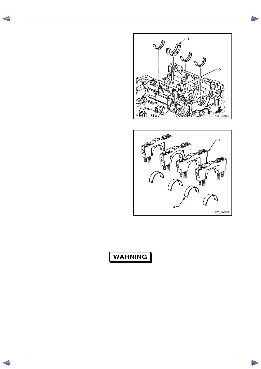
2 

Remove the crankshaft upper bearing halves from the 
cylinder block. Note the position of the thrust 
bearing (1) at the number 3 journal (2). 

3 

Place the crankshaft upper bearing halves on the 
cardboard in the correct positions. 


Figure 6A1 – 504 

4 

Remove the crankshaft lower bearing halves (2) from 
the crankshaft bearing caps (1). 

5 

Place the crankshaft lower bearing halves in the 
correct positions on the cardboard. 


Figure 6A1 – 505 

Clean and Inspect 

Crankshaft and Main Bearing Cleaning 


Safety glasses must be worn when using 
compressed air. 

Clean the following components in solvent and then dry with compressed air: 
• 

crankshaft bearings, 

• 

connecting rod bearings, 

• 

crankshaft journals, 

• 

crankpin journals, 

• 

crankshaft oil passages, and 

• 

crankshaft threaded holes. 

Engine Mechanical – V6 

Page 6A1–284 


Page 6A1–284 

Crankshaft and Main Bearing Visual Inspection 

1 

Perform the following visual inspections: 
• 

Inspect the crankshaft balancer bolt hole (1) for 
thread damage. 

• 

Inspect the crankshaft balancer mounting 
area (2) for damage. 

• 

Inspect the crankshaft sprocket pin hole (3) for 
damage. 

• 

Inspect the oil pump drive flats (4) for damage. 

• 

Inspect the crankshaft main journals (5) for 
damage. 

• 

Inspect the crankshaft connecting rod 
journals (6) for damage. 

• 

Inspect the crankshaft oil passages (7) for 
obstructions. 

• 

Inspect the crankshaft main bearing thrust wall 
surfaces (8) for damage. 

• 

Inspect the crankshaft counterweights (9) for 
damage. 

• 

Inspect the crankshaft reluctor ring teeth (10) for 
damage. 

• 

Inspect the crankshaft rear main oil seal surface 
(11) for damage. 

• 

Inspect the crankshaft engine flexplate 
mounting surface (12) for damage. 

• 

Inspect the crankshaft pilot hole (13) for 
damage. 

• 

Inspect the crankshaft engine flywheel bolt 
holes (14) for thread damage. 

2 

Repair or replace the crankshaft as required. 


Figure 6A1 – 506 


Engine Mechanical – V6 

Page 6A1–285 


Page 6A1–285 

Crankshaft Main Bearing Inspection 

CAUTION


All connecting rod and main journal bearings 
that have been used in a running engine must 
be replaced. Never re-use the crankshaft or 
connecting rod bearings. 

N O T E  

The following bearing wear conditions should be 
used to diagnose engine operating conditions or 
root cause of a condition. 

1 

Inspect for fatigue indicated by craters or pockets (2). 
Flattened sections on the bearing halves (1) also 
indicate fatigue. 


Figure 6A1 – 507 

2 

Inspect for excessive scoring or discoloration (2) on 
both front and back of the bearing halves (1). 

3 

Inspect the main bearings for dirt embedded into the 
bearing material. 


Figure 6A1 – 508 

Engine Mechanical – V6 

Page 6A1–286 


Page 6A1–286 

4 

Inspect for incorrect seating indicated by bright, 
polished sections (1). 


Figure 6A1 – 509 

Crankshaft Measurement 

1 

Using a suitable fixture (1), support the crankshaft (2).


Figure 6A1 – 510 

2 

Using a dial indicator (1) and magnetic base (2), 
rotate the crankshaft (3) carefully by hand. Measure 
the crankshaft main journals for runout and compare 
with the engine specifications, refer to  

5  Specifications

. 


Figure 6A1 – 511 


Content   ..  763  764  765  766   ..