Isuzu KB P190. Manual - part 758
 

  Index      Isuzu     Isuzu KB P190 - service repair manual 2007 year


Search            


Content   ..  756  757  758  759   ..


Isuzu KB P190. Manual - part 758


Engine Mechanical – V6 

Page 6A1–255 


Page 6A1–255 

Disassemble 

1 

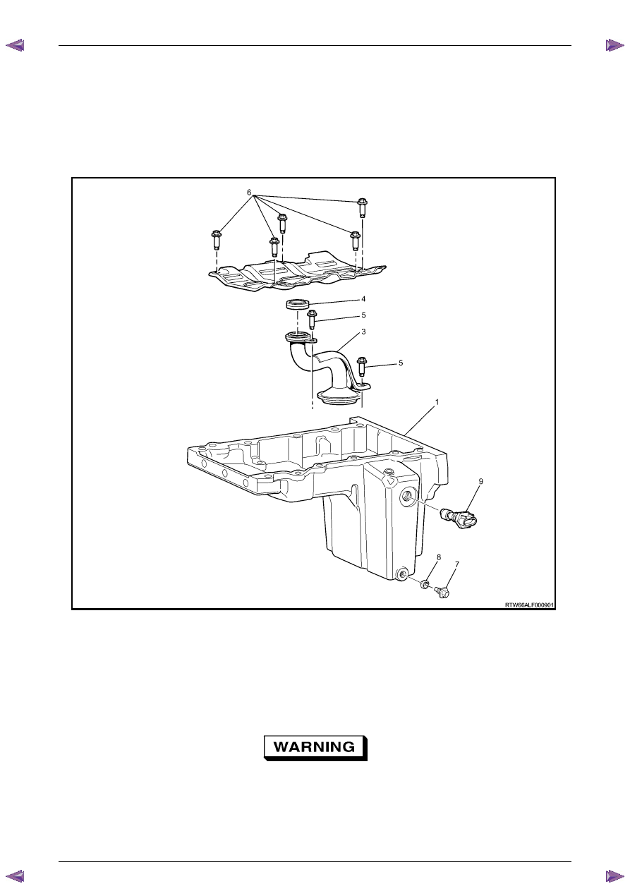
Remove the following: 

2 

Oil pan drain plug (7) and sleeve (8). 

3 

Oil level sensor (9). 

4 

Crankshaft oil deflector bolts (6) and remove the deflector. 

5 

Oil pump suction pipe bolts (5) and the suction pipe (3). 

6 

Oil pump suction pipe gasket (4) from the suction pipe and discard. 


Figure 6A1 – 444 

Clean 

1 

Remove any remaining thread sealant, gasket material or sealant using a commercially available wooden or plastic 
scraper. 

2 

Clean the oil pan and oil pan components in solvent. 

3 

Clean out debris from the bolt holes. 


Safety glasses must be worn when using 
compressed air. 

4 

Dry the oil pan and oil pan components with compressed air. 

Engine Mechanical – V6 

Page 6A1–256 


Page 6A1–256 

Inspect 

1 

Inspect the exterior of the oil pan for the following 
conditions: 
• 

Damage to the drain plug or drain plug hole, 

• 

Damage to the transmission mounting bosses, 

• 

Damage to the oil level sensor threads, and 

• 

Dents or damage to the exterior. 

2 

Inspect the interior of the oil pan for the following 
conditions: 
• 

Gouges or damage to the oil pan sealing 
surfaces, 

• 

Damage to the crankshaft oil deflector, 

• 

Damage to the bolt holes, 

• 

Damage to the oil suction tube mounting 
bosses, and 

• 

Damage to the crankshaft oil deflector mounting 
bosses. 


Figure 6A1 – 445 

3 

Inspect the oil pan deflector for damage. 

4 

Repair or replace the oil pan deflector and/or oil pan 
as required. 


Figure 6A1 – 446 

5 

Inspect the following: 

6 

The mounting face (1) of the oil pump suction pipe for 
possible leakage paths. 

7 

The oil pump pipe support bracket (2) for cracks or 
damage. 

8 

The oil pump suction pipe tube (3) for cracks, 
imperfections and/or damage. 

9 

The oil pump screen (4) for blockage, foreign 
material, tears, cracks and/or damage. 

10 

Repair or replace the oil pan and/or oil pan 
components as required. 


Figure 6A1 – 447 

Engine Mechanical – V6 

Page 6A1–257 


Page 6A1–257 

Reassemble 

Reassembly of the oil pan and oil suction pipe assembly is the reverse of the disassembly procedure, noting the 
following: 

1 

Install a new oil suction tube seal onto the oil suction 
tube. 

2 

Install the oil suction pipe and tighten the attaching 
bolts to the correct torque specification. 

Oil suction pipe attaching  
bolt torque specification .....................................10.0 Nm 

3 

Install the crankshaft oil deflector into the oil pan 
assembly and tighten the attaching bolts to the 
correct torque specification. 

Crankshaft oil deflector 
attaching bolt torque specification......................10.0 Nm 

4 

Install the oil level sensor into the oil pan assembly 
and tighten to the correct torque specification. 

Oil level sensor torque specification...................20.0 Nm 


Figure 6A1 – 448 

5 

Install the oil pan drain plug into the oil pan assembly and tighten to the correct torque specification. 

Oil pan drain plug  
torque specification ............................................25.0 Nm 

Reinstall 

1 

Install the guide pins, Tool No. EN-46109 (1) into the 
oil pan rail bolt hole on each side of the engine block. 


Figure 6A1 – 449 

Engine Mechanical – V6 

Page 6A1–258 


Page 6A1–258 

2 

Place a 3mm bead (1) of RTV sealant on the cylinder 
block pan rail and crankshaft rear oil seal housing to 
oil pan mating surfaces. 

3 

Position the oil pan onto the cylinder block. 

4 

Remove the guide pins, Tool No. EN-46109 from the 
cylinder block. 


Figure 6A1 – 450 

5 

Loosely install the oil pan bolts. 

6 

Tighten the oil pan attaching bolts to the correct 
torque specification and in the sequence shown. 


Oil pan to cylinder block attaching 
bolt (1 – 11) torque specification .............20.0 – 26.0 Nm 

Oil pan to crankshaft rear oil 
seal housing attaching bolt (12 – 13) 
torque specification ...................................8.0 – 12.0 Nm 


Figure 6A1 – 451 


Content   ..  756  757  758  759   ..