Isuzu KB P190. Manual - part 745
 

  Index      Isuzu     Isuzu KB P190 - service repair manual 2007 year


Search            


Content   ..  743  744  745  746   ..


Isuzu KB P190. Manual - part 745


Engine Mechanical – V6 

Page 6A1–203 


Page 6A1–203 

Left-hand Side 

1 

Remove the left-hand cylinder head camshaft sprockets, refer to 

3.18  Camshaft Sprocket

. 

N O T E  

Tool No. EN-46105–1 was installed as part of the 
left-hand cylinder head camshaft sprocket 
removal procedure. 

2 

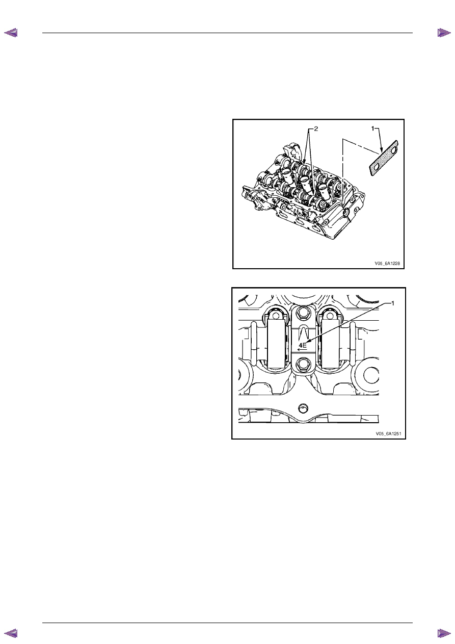
Remove Tool No. EN-46105–1 (1) from the left-hand 
camshafts. 


N O T E  

Tool No. EN-46105 was installed as part of the 
left-hand cylinder head camshaft position 
actuator removal procedure. 


Figure 6A1 – 332 

3 

Observe the markings (1) on the bearing caps. Each 
bearing cap is marked in order to identify its location. 
The markings have the following meanings: 
• 

The raised feature must always be oriented 
toward the centre of the cylinder head. 

• 

An I indicates the intake camshaft. 

• 

An E indicates the exhaust camshaft. 

• 

The number indicates the journal position from 
the front of the engine. 


Figure 6A1 – 333 

Engine Mechanical – V6 

Page 6A1–204 


Page 6A1–204 

4 

Remove the camshaft bearing cap bolts (1) and 
caps (2). 


Figure 6A1 – 334 

5 

Remove the camshafts (1). 


Figure 6A1 – 335 

Clean 

1 

Clean the camshaft in solvent. 


Safety glasses must be worn when using 
compressed air. 

2 

Dry the camshaft with compressed air. 

Engine Mechanical – V6 

Page 6A1–205 


Page 6A1–205 

Inspect 

Camshaft Visual Inspection 

1 

Inspect the threaded hole (2) for damage. 

2 

Inspect the camshaft sprocket locating notch (3) for 
damage or wear. 

3 

Inspect the camshaft sealing grooves (4) for damage.

4 

Inspect the camshaft thrust surface (5) for damage. 

5 

Inspect the camshaft lobes (6) and journals (7) for the 
following conditions: 
• 

Excessive scoring or pitting 

• 

Discoloration from overheating 

• 

Deformation from excessive wear, especially 
the camshaft lobes 

6 

If any of the above conditions exist on the camshaft, 
replace the camshaft. 


Figure 6A1 – 336 

Camshaft Measurement 

1 

With the camshaft (1) in a suitable fixture (2), 
measure the camshaft for wear. 

2 

For camshaft measurement, refer to the following 
specifications, 

5  Specifications

. 


N O T E  

If the camshaft measures outside the specified 
range, replace the camshaft. 

CAUTION


No machining of the camshaft is allowed. 


Figure 6A1 – 337 

3 

Measure the camshaft (2) journals for diameter and 
out-of-round using an outside micrometer (1). 


Figure 6A1 – 338 

Engine Mechanical – V6 

Page 6A1–206 


Page 6A1–206 

4 

Measure the camshaft runout using a dial 
indicator (1). 


Figure 6A1 – 339 

5 

Measure the camshaft thrust width for wear using a 
depth micrometer (A). 


Figure 6A1 – 340 

6 

Measure the camshaft thrust wall surface for runout 
using a dial indicator (1). 


Figure 6A1 – 341 


Content   ..  743  744  745  746   ..