Isuzu KB P190. Manual - part 737
 

  Index      Isuzu     Isuzu KB P190 - service repair manual 2007 year


Search            


Content   ..  735  736  737  738   ..


Isuzu KB P190. Manual - part 737


Engine Mechanical – V6 

Page 6A1–171 


Page 6A1–171 

25 

Verify the proper placement of the right-hand 
secondary timing chain tensioner gasket tab (1). 

26 

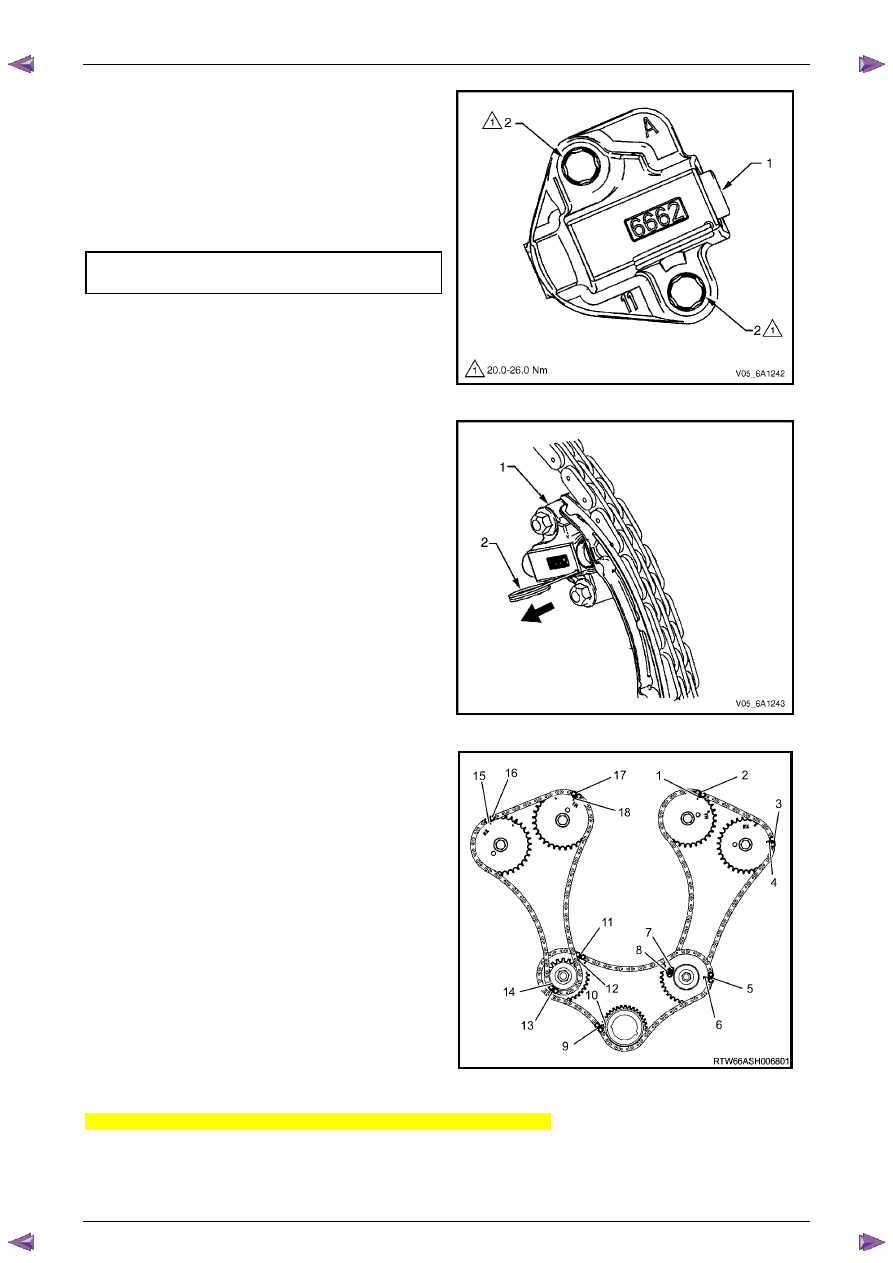
Tighten the right-hand secondary timing chain 
tensioner bolts (2) to the correct torque specification. 


Secondary timing chain tensioner 
attaching bolt torque specification...........20.0 – 26.0 Nm 


Figure 6A1 – 260 

27 

Release the right-hand timing chain tensioner (1) by 
pulling out Tool No. EN 46112 (2) and unlocking the 
tensioner plunger. 


Figure 6A1 – 261 

28 

Verify all primary and secondary timing chain timing 
mark alignments (1 to 18). 

29 

Remove Tool No. EN 46105 and EN 46105-2 from 
the left and right-hand cylinder head camshafts. 

30 

Reinstall the spark plugs. Refer to 

Section 6C1-3 

Engine Management – V6 – Service Operations

. 

31 

Reinstall the engine front cover assembly, refer to 

3.15  Front Cover Assembly

. 


Figure 6A1 – 262 

Right-hand Secondary Timing Chain Components – MY06 Update 

1 

Install the primary timing chain components, refer to Primary Timing chain Components in this Section. 

Engine Mechanical – V6 

Page 6A1–172 


Page 6A1–172 

2 

Using Tool No. EN46111 (1), rotate the crankshaft in 
a clockwise direction until the crankshaft sprocket 
timing mark (2) is aligned with the indexing mark (3) 
on the oil pump housing. 


Figure 6A1 – 263 

CAUTION


In order to install Tool No. EN 46105 onto the 
camshafts, rotate the camshafts. There 
should be no need to rotate the camshaft 
more than 45 degrees. 


Figure 6A1 – 264 

3 

Install Tool No. EN 46105–1 (1) onto the rear of the 
right-hand cylinder head camshafts (2). 


Figure 6A1 – 265 

Engine Mechanical – V6 

Page 6A1–173 


Page 6A1–173 

4 

Install Tool No. EN 46105–2 (1) onto the rear of the 
left-hand cylinder head camshafts (2). 


Figure 6A1 – 266 

5 

Install the right-hand secondary timing chain (1) onto 
the camshaft sprockets (2) and the right hand 
camshaft intermediate sprocket (3) aligning the chain 
in the following manner: 


Figure 6A1 – 267 

6 

Place the secondary timing chain around the right-
hand camshaft intermediate outer sprocket, aligning 
the bright plated timing chain link (1) with the 
alignment access hole (2) in the inner sprocket. 


Figure 6A1 – 268 

Engine Mechanical – V6 

Page 6A1–174 


Page 6A1–174 

7 

Wrap the secondary timing chain around both right-
hand camshaft drive sprockets. 


Figure 6A1 – 269 

CAUTION


Ensure that when aligning the right-hand 
secondary timing chain to the right-hand 
camshaft sprockets, that the triangular 
timing marks (1) on the sprocket are used, 
NOT the circular mark. 

8 

Align the bright plated timing chain link (2) with the 
exhaust sprocket alignment triangle mark or circular 
mark. 


Figure 6A1 – 270 

9 

Align the bright plated timing chain link (1) with the 
intake sprocket alignment triangle mark (2). 


Figure 6A1 – 271 


Content   ..  735  736  737  738   ..