Isuzu KB P190. Manual - part 727
 

  Index      Isuzu     Isuzu KB P190 - service repair manual 2007 year


Search            


Content   ..  725  726  727  728   ..


Isuzu KB P190. Manual - part 727


Engine Mechanical – V6 

Page 6A1–131 


Page 6A1–131 

3 

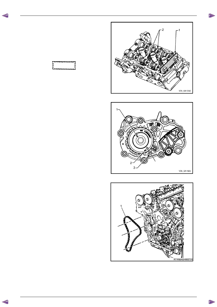
Install Tool No. EN 46105-1 (1) onto the rear of the 
left-hand cylinder head camshafts (2), and Tool No. 
EN 46105-2 onto the rear of the right-hand cylinder 
head camshafts. 

4 

Ensure that Tool No. EN 46105 is fully seated onto 
the camshafts. 


CAUTION


All camshafts must be locked in place before 
installation of any timing chains. 


Figure 6A1 – 147 

5 

Using Tool No. EN46111 (1), rotate the crankshaft in 
a clockwise direction until the crankshaft sprocket 
timing mark (2) is aligned with the indexing mark (3) 
on the oil pump housing. 


Figure 6A1 – 148 

6 

Install the left-hand secondary timing chain (1) 
aligning the chain in the following manner: 


Figure 6A1 – 149 

Engine Mechanical – V6 

Page 6A1–132 


Page 6A1–132 

7 

Wrap the secondary timing chain around both left-
hand camshaft drive sprockets. 

8 

Ensure there are two bright links located on top of 
each of the camshaft sprockets. 


Figure 6A1 – 150 

CAUTION


When aligning the left-hand secondary timing 
chain to the camshaft sprockets, ensure the 
circular timing marks on the sprocket are 
used, NOT the triangular mark. 

9 

Align the bright plated timing chain link (1) with the 
left-hand exhaust camshaft position sprocket 
alignment circle mark (2). 


Figure 6A1 – 151


Engine Mechanical – V6 

Page 6A1–133 


Page 6A1–133 

10 

Align the bright plated timing chain link (1) with the 
intake camshaft position sprocket alignment circle 
mark (2). 


Figure 6A1 – 152 

11 

Ensure the left-hand camshaft intermediate sprocket 
is selected and orientated correctly. 


CAUTION


The left-hand camshaft intermediate 
sprocket (1) is marked with the letters LB 
and ‘FRONT’, and the right-hand sprocket (2) 
is marked with the letters RB and 'FRONT' 
Ensure the correct sprocket is used and the 
'FRONT' text is facing forwards when 
installed. 


Figure 6A1 – 153 

12 

Place the left-hand secondary timing chain around the 
left-hand camshaft intermediate inner sprocket, with 
the bright plated timing chain link (1) aligned with the 
access hole (2) in the outer sprocket. 


Figure 6A1 – 154 

Engine Mechanical – V6 

Page 6A1–134 


Page 6A1–134 

13 

Install the left-hand camshaft intermediate sprocket to 
the cylinder block. 

14 

Install the sprocket bolt (1) and tighten to the correct 
torque specification. 


Camshaft intermediate sprocket 
attaching bolt torque specification...........58.0 – 72.0 Nm 


Figure 6A1 – 155 

15 

Verify the left-hand secondary timing chain timing 
mark alignments (1 to 6) 


Figure 6A1 – 156 

16 

Ensure the left-hand secondary timing chain guide is 
selected and orientated correctly. 


CAUTION


The left-hand secondary timing chain guide 
is marked with the letters LH. Ensure the 
correct shoe is used when installing to the 
left-hand side in this procedure and that the 
letters ‘LH” are facing the front of the vehicle 
when installed.  


Figure 6A1 – 157 


Content   ..  725  726  727  728   ..