Isuzu KB P190. Manual - part 647
 

  Index      Isuzu     Isuzu KB P190 - service repair manual 2007 year


Search            


Content   ..  645  646  647  648   ..


Isuzu KB P190. Manual - part 647


Engine Mechanical – V6 

Page 6A1–109 


Left-hand Secondary Timing Chain Shoe 

1 

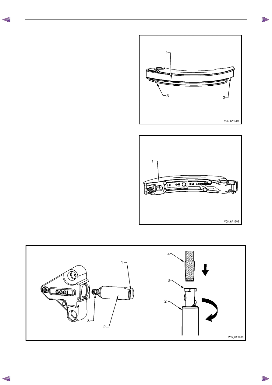
Inspect the front of the left-hand secondary timing 
chain shoe for the following: 
• 

worn shoe surface (1), 

• 

cracked or broken shoe surface (2), and 

• 

cracked or damaged shoe (3). 

Figure 6A1 – 135 

2 

Inspect the back of the shoe for a damaged, worn or 
missing timing chain tensioner contact pad (1). 

3 

Replace a damaged shoe as required. 


Figure 6A1 – 136 

Left-hand Secondary Timing Chain Tensioner 


Figure 6A1 – 137 

1 

Inspect the left-hand secondary timing chain tensioner for damaged plunger-to-shoe contact surface (1), refer to 
Figure 6A1 – 137. 

Engine Mechanical – V6 

Page 6A1–110 


2 

Inspect the tensioner for locked or binding tensioner shaft (2). Reset the plunger (3) and ensure the tensioner shaft 
moves freely in and out of the body of the tensioner. 

N O T E  

To reset the tensioner, use a suitably sized flat 
blade screwdriver or Tool No. J 45027 (4) to wind 
the plunger in a clockwise direction, into the 
tensioner shaft. 

3 

Replace a damaged tensioner as required. 

Right-hand Secondary Timing Chain Guide 

1 

Inspect the right-hand secondary timing chain guide 
for the following: 
• 

worn guide surface (1), 

• 

cracked or broken guide surface (2), and 

• 

cracked or damaged guide base (3). 

2 

Replace a damaged guide as required. 


Figure 6A1 – 138 

Right-hand Secondary Timing Chain Shoe 

1 

Inspect the front of the right-hand secondary timing 
chain shoe for the following: 
• 

worn shoe surface (1), 

• 

cracked or broken shoe surface (2), and 

• 

cracked or damaged shoe (3). 


Figure 6A1 – 139 

Engine Mechanical – V6 

Page 6A1–111 


2 

Inspect the back of the shoe for a damaged, worn or 
missing timing chain tensioner contact pad (1). 


Replace a damaged shoe as required. 

Figure 6A1 – 140 

Right-hand Secondary Timing Chain Tensioner 


Figure 6A1 – 141 

1 

Inspect the right-hand secondary timing chain tensioner for damaged plunger-to-shoe contact surface (1), refer to 
Figure 6A1 – 141. 

N O T E  

To reset the tensioner, use a suitably sized flat 
blade screwdriver or Tool No. J 45027 (4) to wind 
the plunger in a clockwise direction, into the 
tensioner shaft. 

2 

Inspect the tensioner for a locked or binding tensioner shaft (2). Reset the plunger (3) and ensure the tensioner 
shaft moves freely in and out of the body of the tensioner. 

3 

Replace a damaged tensioner as required. 

Reinstall 

Left-hand Secondary Timing Chain Components 


Engine Mechanical – V6 

Page 6A1–112 


1 

Install the crankshaft sprocket (1) onto the 
crankshaft (2) by aligning the keyway to the key on 
the crankshaft. 

2 

Slide the crankshaft sprocket on the crankshaft until 
the crankshaft sprocket contacts the step in the 
crankshaft. 


Figure 6A1 – 142 

N O T E  

Ensure that the crankshaft sprocket is installed 
with the timing mark (1) visible. 

Figure 6A1 – 143 

CAUTION


In order to install Tool No. EN 46105 onto the 
camshafts, rotate the camshafts in an anti-
clockwise direction. There should be no 
need to rotate the camshaft more than 45 
degrees. 

Figure 6A1 – 144 


Content   ..  645  646  647  648   ..