Isuzu KB P190. Manual - part 592
6E–198
ENGINE DRIVEABILITY AND EMISSIONS
9
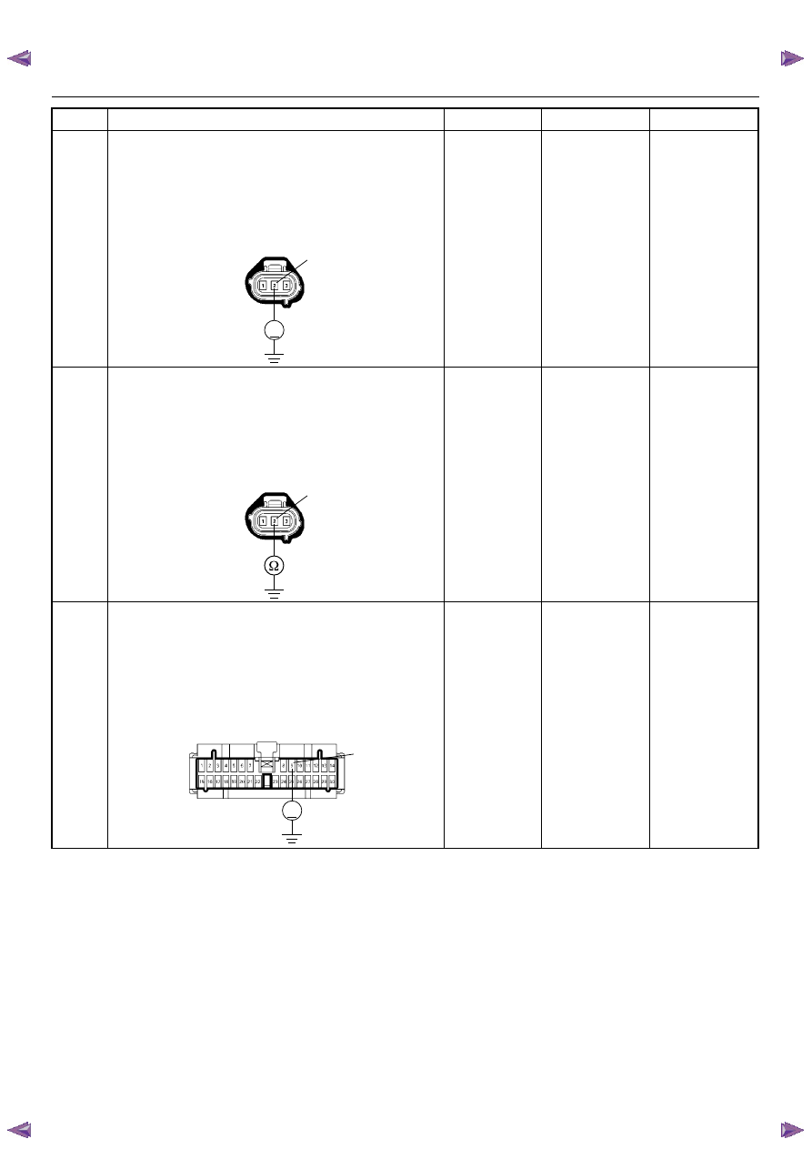
Using the DVM and check the VSS ground circuit.
1. Ignition “On”, engine “Off”.
2. Disconnect the VSS connector.
3. Check the circuit for short to power supply circuit.
Was the DVM indicated specified value?
Less than 1V
Go to Step 10
Repair faulty
harness and
verify repair
10
Using the DVM and check the VSS ground circuit.
1. Ignition “Off”, engine “Off”.
2. Disconnect the VSS connector.
3. Check the circuit for open circuit.
Was the problem found?
—
Repair faulty
harness and
verify repair
Go to Step 19
11
Using the DVM and check the VSS signal circuit.
1. Ignition “On”, engine “Off”.
2. Disconnect the VSS connector and meter
connector.
3. Check the circuit for short to power supply circuit.
Was the DVM indicated specified value?
Less than 1V
Go to Step 12
Repair faulty
harness and
verify repair
Step
Action
Value(s)
Yes
No
V
E-44
2
E-44
2
V
B-24
9