Isuzu KB P190. Manual - part 560


  Index      Isuzu     Isuzu KB P190 - service repair manual 2007 year


Search            


Content   ..  558  559  560  561   ..


Isuzu KB P190. Manual - part 560


6E–70

ENGINE DRIVEABILITY AND EMISSIONS

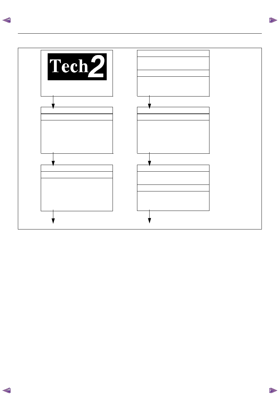
Tech 2 Operating Flow Cart (Start Up)

Select “2.XL L4 HV240” in Vehicle Identification menu and the following table is shown in the Tech 2 screen.

System Selection Menu

F0: Powertrain

F1: Chassis

F3: Body

Select “(TF/UC)”.

Vehicle Identification

4JH1-TC Bosch

4JH1-T Denso

2.XL L4 HV240

3.5L V6 6VE1 Hitachi

AW30-40LE

AT JR405E

Select “F0: Powertrain”.

Main Menu

F0: Diagnostic

F1: Service Programming System (SPS)

F2: View Capture Data

F3: Tool Option

F4: Download/ Upload Help

Press “ENTER” key.

Vehicle Identification

(3) 2003

(2) 2002

(1) 2001

(Y) 2000

(X) 1999

(W) 1998

Select “F0: Diagnostic”.

Select “(3) 2003” or later.

Press (ENTER) to Continue

Select “2.XL L4 HV240”.

Vehicle Identification

(UB) Trooper, Bighorn

(UE) Rodeo,/Amigo, Wizard/Mu

(TF/UC) LUV, Frontier, LAO-Rodeo

(TBR)

(N*) ELF, NPR, NQR

ENGINE DRIVEABILITY AND EMISSIONS

6E–71

F0: Diagnostic Trouble Code
The purpose of the “Diagnostic Trouble Codes” mode is
to display stored trouble code in the ECM.
When “Clear DTC Information” is selected, a “Clear
DTC Information”, warning screen appears. 
This screen informs you that by cleaning DTC's “all
stored DTC information in the ECM will be erased”.
After clearing codes, confirm system operation by test
driving the vehicle.
Use the “DTC Information” mode to search for a specific
type of stored DTC information. 

History
This selection will display only DTCs that are stored in
the ECM's history memory. It will not display Type B
DTCs that have not requested the MIL (“Check Engine

Lamp”). It will display all type A and B DTCs that
requested the MIL and have failed within the last 40
warm-up cycles. In addition, it will display all type C and
D DTCs that have failed within the last 40 warm-up
cycles.       

MIL SVC or Message Request
This selection will display only DTCs that are requesting
the MIL. Type C and Type D DTCs cannot be displayed
using the MIL. Type C and D DTCs cannot be displayed
using this option. 
This selection will report type B DTCs only after the MIL
has been requested.

Last Test Failed
This selection will display only DTCs that have failed the
last time the test run. The last test may have run during
a previous ignition cycle of a type A or type B DTC is
displayed. For type C and type D DTCs, the last failure
must have occurred during the current ignition cycle to
appear as last test fail.

Test Failed Since Code Cleared
The selection will display all active and history DTCs
that have reported a test failure since the last time
DTCs were cleared. DTCs that last failed more that 40
warm-up cycles before this option is selected will not be
displayed.

No Run Since Code Cleared
This selection will display up to DTCs that have not run
since the DTCs were last cleared. Since any displayed
DTCs have not run, their condition (passing or failing) is
unknown.

Failed This Ignition
This selection will display all DTCs  that have failed
during the present ignition cycle.

F1: Data Display
The purpose of the “Data Display” mode is to
continuously monitor data parameters.
The current actual values of all important sensors and
signals in the system are display through F1 mode.
See the “Typical Scan Data” section.

F2: Snapshot
“Snapshot” allows you to focus on making the condition
occur, rather than trying to view all of the data in
anticipation of the fault. 
The snapshot will collect parameter information around
a trigger point that you select.

F3: Miscellaneous Test:
The purpose of “Miscellaneous Test” mode is to check
for correct operation of electronic system actuators.

F0: Diagnostic Trouble Code

F0: Read DTC Infor By Priority

F1: Clear DTC Information

F2: DTC Information

F0: History

F1: MIL SVS or Message Requested

F2: Last Test Failed

F3: Test Failed Since Code Cleared

F4: Not Run Since Code Cleared

F5: Failed This Ignition

F1: Data Display

F0: Engine Data

F1: O

2

 Sensor Data

F2: Snapshot

F3: Miscellaneous Test

F0: Lamps

F0: Malfunction Indicator Lamps

F1: Relays

F0: Fuel Pump Relay

F1: A/C Clutch Relay

F2: EVAP

F0: Purge Solenoid

F3: IAC System

F0: IAC Control

F1: IAC Reset

F4: Injector Balance Test

6E–72

ENGINE DRIVEABILITY AND EMISSIONS

TYPICAL SCAN DATA & DEFINITIONS (ENGINE DATA)

Use the Typical Values Table only after the On-Board Diagnostic  System Check has been completed, no DTC(s) were
noted, and you have determined  that the on-board diagnostics are functioning properly. Tech 2 values from  a
properly-running engine may be used for comparison with the engine you are  diagnosing.
Condition : Vehicle stopping, engine running, air conditioning off & after warm-up (Coolant temperature approximately
80 deg.)

Tech 2 Parameter

Units

Idle

2000rpm

Description

1

Engine Speed

rpm

775 - 875

1950 - 2050

The actual engine speed is measured by ECM from the
CKP sensor 58X signal.

2

Desired Idle Speed

rpm

825

800 

850

The desired engine idle speed that the ECM
commanding. The ECM compensates for various engine
loads.

3

Engine Coolant 
Temperature

°C or °F

80 - 90

80 - 90

The ECT is measured by ECM from ECT sensor output
voltage. When the engine is normally warm upped, this
data displays approximately 80 °C or more.

4

Start Up ECT (Engine
Coolant Temperature)

°C or °F

Depends on ECT 

at start-up

Depends on ECT 

at start-up

Start-up ECT is measured by ECM from ECT sensor
output voltage when engine is started. 

5

Intake Air 
Temperature 

°C or °F

Depends on 

ambient temp

Depends on 

ambient temp

The IAT is measured by ECM from IAT sensor output
voltage. This data is changing by intake air temperature.

6

Start Up IAT (Intake
Air Temperature)

°C or °F

Depends on IAT at 

start-up

Depends on IAT at 

start-up

Start-up IAT is measured by ECM from IAT sensor output
voltage when engine is started. 

7

Manifold Absolute 
Pressure

kPa

31 - 36

25 - 30

The MAP (kPa) is measured by ECM from MAP output
voltage. This data is changing by inlet manifold pressure.

8

Barometric Pressure

kPa

Depends on 

altitude

Depends on 

altitude

The barometric pressure is measured by ECM from the
MAP sensor output voltage monitored during key up and
wide open throttle. This data is changing by altitude.

9

Throttle Position

%

0

2-4

Throttle position operating angle is measured by the
ECM from throttle position output voltage. This should
display 0% at idle and 99 - 100% at full throttle. 

10

Calculated Air Flow

g/s

3.5 -4.50

8.0 - 10.0

This displays calculated air mount from MAP sensor
output. This data is changing by inlet manifold pressure.

11

Air Fuel Ratio

14.6:1

14.6:1

This displays the ECM commanded value. In closed loop,
this should normally be displayed around 14.2:1 - 14.7:1. 

12

Spark Advance

°CA

8 - 15

25 

32

This displays the amount of spark advance being
commanded by the ECM.

13

Engine Load

%

2 - 5

5 - 10

This displays is calculated by the ECM form engine
speed and MAF sensor reading. Engine load should
increase with an increase in engine speed or air flow
amount.

14

Injection Pulse Width

ms

1.0 - 3.0 

3.0 

4.0

This displays the amount of time the ECM is
commanding each injector On during each engine cycle.
A longer injector pulse width will cause more fuel to be
delivered.  Injector pulse width should increase with
increased engine load.

15

Fuel System Status 

Open Loop/
Close Loop

Close Loop

Close Loop

When the engine is first started the system is in “Open
Loop” operation. In “Open Loop”, the ECM ignores the
signal from the oxygen sensors. When various conditions
(ECT, time from start, engine speed & oxygen sensor
output) are met, the system enters “Closed Loop”
operation. In “Closed Loop”, the ECM calculates the air
fuel ratio based on the signal from the oxygen sensors. 

16

Knock Present

Yes/No

No

No

This displays knock sensor detection status. When
engine knock is occurred, displays "Yes".

17

Knock Counter

-

-

This displays the number of knock during a ignition cycle.

18

Knock  Retard

°CA

0

0

This displays the commanded ignition spark timing retard
timing based on the signal from the knock sensor.

19

A/C Clutch Relay

On/Off

Off

Off

This displays whether the ECM has commanded the A/C
compressor clutch “On” or “Off”.

ENGINE DRIVEABILITY AND EMISSIONS

6E–73

20

A/C Request 

Yes/No

Off

Off

This displays the air conditioner request signal. This
should display “On” when the air conditioner switch is
switched on.

21

EVAP Purge Solenoid 
(Evaporative
Emission)

%

0 - 10

0 - 10

This displays the duty signal from the ECM to control the
canister purge solenoid valve.

22

Fuel Pump

On/Off

On

On

This displays operating status for the fuel pump main
relay. This should display “On” when the key switch is
turned on and while engine is running.

23

Idle Air Control

Steps

20 - 30

65 - 75

This displays the ECM commanded position of the idle air
control valve pintle. A larger number means that more air
is being commanded through the idle air passage. 

24

Idle Speed Variation

rpm

-25 - 0

1125 - 1225 

This displays variation of actual engine speed & desired
idle speed.

25

Vehicle Speed

km/h or 
mph

0

0

This displays vehicle speed. The vehicle speed is
measured by ECM from the vehicle speed sensor.

26

Ignition Voltage

V

10.0 - 14.5

10.0 - 14.5

This displays the system voltage measured by the ECM
at ignition feed.

27

Reference Voltage

V

5.00

5.00

28

Malfunction Indicator
Lamp

On/Off

Off

Off

This displays operating status for the Check Engine
Lamp. This should display “On” when the Check Engine
Lamp is turned on.

29

Time From Start

-

-

This displays the engine time elapsed since the engine
was started. If the engine is stopped, engine run time will
be reset to 00:00:00

Tech 2 Parameter

Units

Idle

2000rpm

Description


Content   ..  558  559  560  561   ..