Isuzu KB P190. Manual - part 266
 

  Index      Isuzu     Isuzu KB P190 - service repair manual 2007 year


Search            


Content   ..  264  265  266  267   ..


Isuzu KB P190. Manual - part 266


6E-30  Engine Control System (4JH1) 

Diagnostic Information And Prosedures 

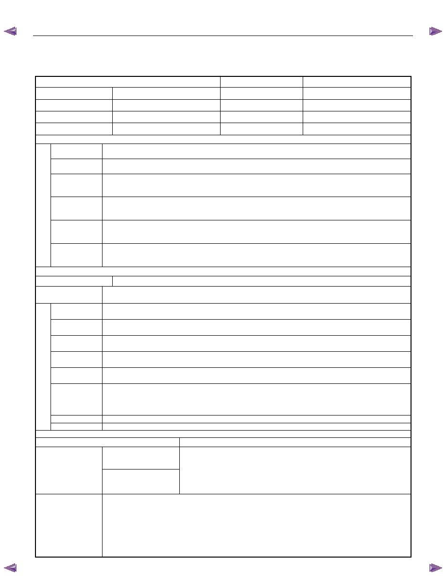
Engine Control System Check Sheet 


ENGINE CONTROL SYSTEM CHECK SHEET 

Inspectors Name 


Customer’s Name 


Model & Model Year 


Driver’s Name 


Chassis No. 


Date Vehicle Brought In   

Engine No. 


License No. 


Odometer Reading 

Km/miles


□


Engine Does 
Not Run 

□

  Engine does not crank 

□

No initial combustion 

□

  No complete combustion 

□

  Hard Start 

□

  Engine cranks slowly 

□

Other ( 


)

□

  Abnormal idling speed  

□

High idling speed (             RPM)

□

  Low idling speed (              RPM)

□

  Rough 

idling 


□

  Incorrect Idle 

□

  Other ( 


)

□

  Hesitation, sag, stumble 

□

Surge, chuggles 

□

  Cut out, misses 

□

  Lack of power, sluggishness, sponginess 


□


Poor 
Driveability 

□

  Other ( 


)


□

  Soon after starting 

□

After accelerator pedal depressed 

Engine Stall 

□

  During A/C operation 

□

After accelerator pedal released 

□

  Shifting from N to D 

□


□

  Other ( 


)

□

  Black smoke 

□

White smoke 

□

  Poor fuel economy 

□

  Fuel knock, combustion noise 


P

roblem

 S

ym

pt

om

s 

□

  Others 

□

  Other ( 


)

Dates problem occurred 


□

  Constant 

□

Intermittently (           times per       day/month) 

□

  Once only 

Problem frequency 

□

  Other ( 


)

□

  Fine  

□

Cloudy 

□

Rainy 

□

  Snow 

Weather 

□

  Various/Other ( 


)

□

  Hot (approx.               )  □ Warm 

□

Cool 

□

  Cold (approx.             )

Outside 
Temperature 

□

  Any 

temperature 


□

  Highway 

□

Suburbs 

□

City area 

□

  Uphill 

Place 

□

  Downhill 

□

Rough road 

□

Other ( 


)

□

  Over (approx. 

tons)


□

No load 


Load Condition 

□

  Other (approx. 

tons)


□

  Cold 

□

Warming up 

□

After warming up 

□

  Any temperature 

Engine 
Temperature 

□

  Other ( 


)

□

  Starting 

□

Just after starting ( 


Min.) 

□

  Idling 

□

  Racing 

□

Driving 

□

Constant speed 

□

  Acceleration 

□

  Deceleration 

□

A/C switch On/Off 


Engine Operation 

□

  Other ( 


)

Fuel Amount 

□

  Full 

□

Above 1/2 

□

Below 1/2 

□

  Near empty 

Condit

ion When P

roblem

 Oc

cu

rs


Fuel 

Bland 


Condition of MIL 

□

Remains On 

□

Intermittently turns On 

□

  Does not turn On 

Present Code 

□

Nothing 

□

P Code & Symptom Code 
No. ( 

)

Diagnostic Trouble 
Code (DTC) or Flash 
Code 

History Code 

□

Nothing 

□

P Code & Symptom Code 
No. ( 

)


Other Additional 
Condition 


Engine Control System (4JH1)  6E-31 

Diagnostic Starting Point - Engine Controls

Begin the system diagnosis with Diagnostic System
Check - Engine Controls. The Diagnostic System Check
- Engine Controls will provide the following information:

• The identification of the control modules which

command the system. 

•  The ability of the control modules to communicate

through the serial data circuit. 

• The identification of any stored diagnostic trouble

codes (DTCs) and the their statuses. 

The use of the Diagnostic System Check - Engine 
Controls will identify the correct procedure for
diagnosing the system and where the procedure is
located. 
Important: 
Engine Control System Check Sheet must be used to
verify the complaint vehicle, you need to know the
correct (normal) operating behavior of the system and
verify that the customer complaint is a valid failure of
the system. 


Reading Flash Diagnostic Trouble Codes 
The provision for communicating with the ECM is the 
Data Link Connector (DLC). The DTCs stored in the
ECM memory can be read either through a hand-held
diagnostic scanner such as scan tool plugged into the 
DLC or by counting the number of flashes of the MIL 
when the diagnostic test terminal of the DLC is 
grounded. The DLC terminal “6” (diagnostic request
switch) is pulled “Low” (grounded) by jumped to DLC
terminal “4”, which is a ground wire. 
Once terminals “4” and “6” have been connected, the 
ignition switch must be moved to the “ON” position, with 
the engine not running. The MIL will initially flash 12. 
Then, the MIL will flash the first stored DTC three times, 
second stored DTC three times and so on. All the
stored DTCs are flashed, then return 12 and continue to 
flash the DTC. If no DTC exists, the MIL flashes 12 
continuously. The flash DTC display will continue as
long as the DLC is shorted.  


RTW66ESF000501 

6E-32  Engine Control System (4JH1) 

Breaker Box


Breaker Box Connection Type A 


RTW66ESH003601

Legend 

1. Engine Control Module (ECM) 
2. Harness Adapter 
3. ECM - Harness Connector 
4. Breaker Box 
5. ECM is disconnected 


Breaker Box Connection Type B 


RTW66ESH003701

Legend 

1.  Engine Control Module (ECM) 
2. Harness Adapter 
3.  ECM - Harness Connector 
4. Breaker Box 
5.  ECM is connected 

 
Although probe to the engine control module (ECM) 
harness connector is possible by Test Adapter, 
Breaker Box Connection Type A is suitable usage to 
prevent misprobe and damage of female terminals 
when test open circuit or short to ground between the 
ECM and electrical components, since the terminals 
where the harness connector of the ECM is thin have 
gathered. 


The ECM and other connectors have water proof 
terminal that is not allowed to back probe. Breaker 
Box Connection Type B is suitable usage to test short 
to voltage circuit or signal check between the ECM 
and electrical components. 


Engine Control System (4JH1)  6E-33 

Diagnostic System Check - Engine

Controls  

Description 
The Diagnostic System Check-Engine Controls is an
organized approach to identifying a condition that is
created by a malfunction in the electronic engine control
system. The Diagnostic System Check must be the
starting point for any driveability concern. The 
Diagnostic System Check directs the service technician
to the next logical step in order to diagnose the concern.
Understanding and correctly using the diagnostic table
reduces diagnostic time, and prevents the replacement
of good parts. 
Test Description 
The numbers below refer to the step numbers on the
diagnostic table. 
2. Lack of communication may be because of a partial
or a total malfunction of the Keyword 2000 serial data
circuit. The specified procedure determines the
particular condition. 


11. If there are other modules with DTCs set, refer to
the DTC list. The DTC list directs you to the appropriate 
diagnostic procedure. If the control module stores
multiple DTCs, diagnose the DTCs in the following
order. 
•  Component level DTCs, such as sensor DTCs, 

solenoid DTCs, actuator DTCs, and relay DTCs. 
Diagnose the multiple DTCs within this category in 
numerical order. Begin with the lowest numbered 
DTC, unless the diagnostic table directs you 
otherwise. 

Important:


•  DO NOT perform this diagnostic if there is not a 

driveability concern, unless another procedure 
directs you to this diagnostic. 

•  Before you proceed with diagnosis, search for 

applicable service bulletins. 

•  Unless a diagnostic procedure instructs you, DO 

NOT clear the DTCs. 

•  If there is a condition with the starting system, refer 

to the starting system section in the engine 
mechanical. 

•  Ensure the battery has a full charge. 
•  Ensure the battery cables (+) (-) are clean and 

tight. 

•  Ensure the ECM grounds are clean, tight, and in 

the correct location. 

•  Ensure the ECM harness connectors are clean and 

correctly connected. 

•  Ensure the ECM terminals are clean and correctly 

mating. 

•  Ensure the fuel injection pump control unit (PCU) 

ground is clean, tight, and in the correct location.  

•  Ensure the PCU harness connectors are clean and 

correctly connected.  

•  Ensure the PCU terminals are clean and correctly 

mating. 

•  Ensure the vehicle maintenance has been done 

enough. 


Step Action 

Value(s) 

Yes 

No 

1 

Install the scan tool. 
Does the scan tool turn ON? 

 

Go to Step 2 

Go to scan tool 

Does Not Power Up


Content   ..  264  265  266  267   ..