Isuzu KB P190. Manual - part 1422


  Index      Isuzu     Isuzu KB P190 - service repair manual 2007 year


Search            


Content   ..  1420  1421  1422  1423   ..


Isuzu KB P190. Manual - part 1422


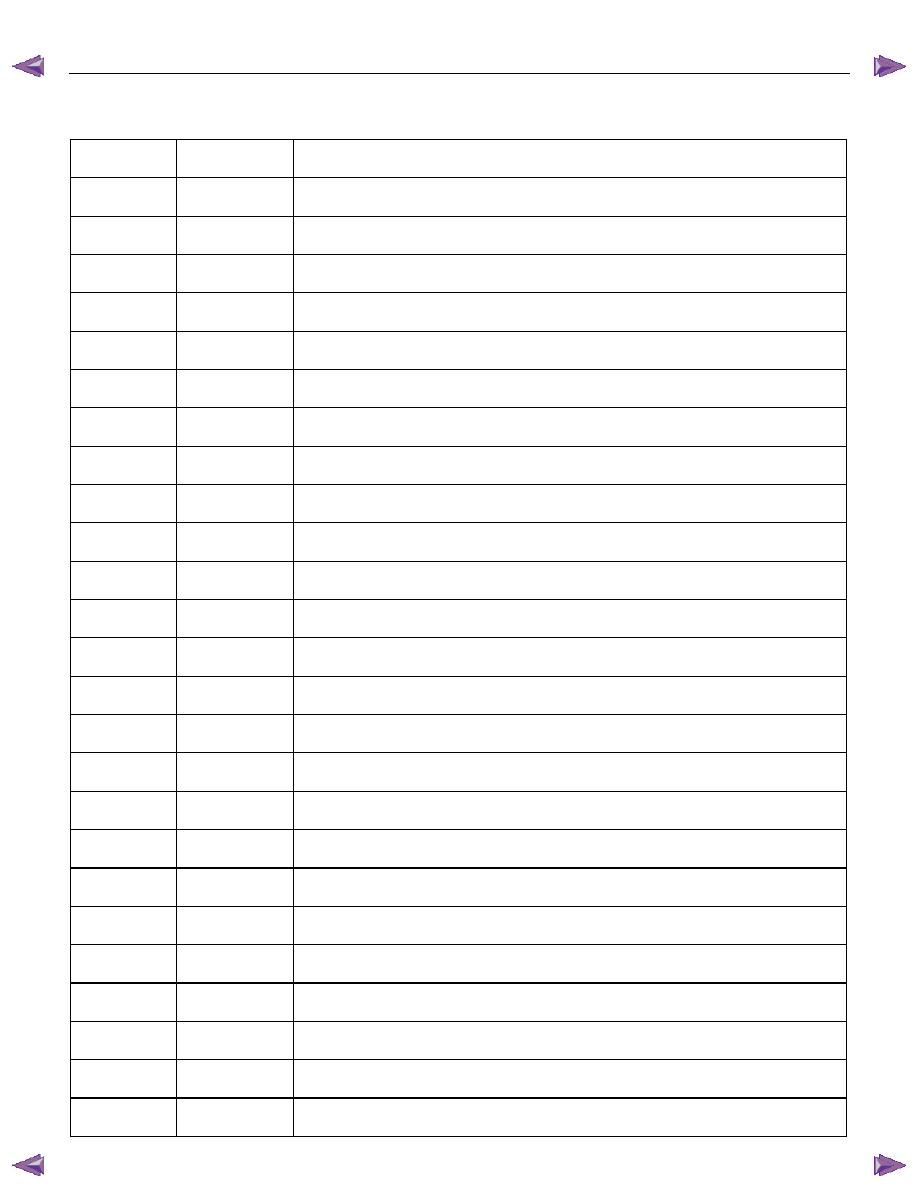
9A1-6  RESTRAINT CONTROL SYSTEM 


Diagnostic Trouble Codes 

Choose and trace an appropriate flowchart by the numbers listed below to find fault and repair. 

DTC Flash 

Code 

Description 

– 

12 

Diagnostic Display Mode (Flash Code only) 

– 

13 

Diagnostic Display Mode (Flash Code only) 

B0015 

15 

Passenger Air Bag Squib Circuit High Resistance 

B0016 

16 

Passenger Air Bag Squib Circuit Low Resistance 

B0018 

18 

Passenger Air Bag Squib Circuit Short to GND 

B0019 

19 

Passenger Air Bag Squib Circuit Short to Battery Voltage 

B0021 

21 

Driver Air Bag Squib Circuit High Resistance 

B0022 

22 

Driver Air Bag Squib Circuit Low Resistance 

B0025 

25 

Driver Air Bag Squib Circuit Short to GND 

B0026 

26 

Driver Air Bag Squib Circuit Short to Battery Voltage 

B0029 

29 

Passenger Pretensioner Squib Circuit High Resistance 

B0031 

31 

Passenger Pretensioner Squib Circuit Low Resistance 

B0033 

33 

Passenger Pretensioner Squib Circuit Short to GND 

B0034 

34 

Passenger Pretensioner Squib Circuit Short to Battery Voltage 

B0041 

41 

Driver Pretensioner Squib Circuit High Resistance 

B0042 

42 

Driver Pretensioner Squib Circuit Low Resistance 

B0045 

45 

Driver Pretensioner Squib Circuit Short to GND 

B0046 

46 

Driver Pretensioner Squib Circuit Short to Battery Voltage 

B0051 

51 

Air Bag Squib Circuit Activated (Clash) 

B0052 

52 

Pretensioner Squib Circuit Activated 

B0055 

55 

Vehicle Variant Missing 

B0061 

61 

Warning Lamp Circuit Failure 

B0062 

62 

Battery Voltage Too High 

B0063 

63 

Battery Voltage Too Low 

B0071 

71 

SRS Control Unit Internal Fault 


RESTRAINT CONTROL SYSTEM  9A1-7 


System Schematic 


RTW79ALF000301 


SRS Diagnostic System Check 

The diagnostic procedures used in this section are
designed to find and repair SRS malfunctions.  To get
the best results, it is important to use the diagnostic
charts and follow the sequence listed below: 
A  Perform the “SRS Diagnostic System Check.” 
 

The “SRS Diagnostic System Check” must be the
starting point of any SRS diagnostics.  The “SRS
Diagnostic System Check” checks for proper “SRS”
warning lamp operation, the ability of the SRS
control unit to communicate through the “Serial
Data” line and whether SRS diagnostic trouble codes
exist. 


B  Refer to the proper diagnostic chart as directed by 

the “SRS Diagnostic System Check.” 


The “SRS Diagnostic System Check” will lead you to 
the correct chart to diagnose any SRS malfunctions. 
Bypassing these procedures may result in extended 
diagnostic time, incorrect diagnosis and incorrect 
parts replacement. 

C  Repeat the “SRS Diagnostic System Check” after

any repair or diagnostic procedures have been 
preformed. 

  Performing the “SRS Diagnostic System Check” 

after all repair or diagnostic procedures will ensure 
that the repair has been made correctly and that no 
other malfunctions exist. 

9A1-8  RESTRAINT CONTROL SYSTEM 


Circuit Description 

When the ignition switch is first turned “ON”, “Ignition 1”
voltage is applied from the “SRS” fuse to the SRS
control unit at the “Ignition 1” input terminals “1”.  The 
SRS control unit responds by flashing the “SRS”
warning lamp seven times, while performing tests on
the SRS. 
 

Notes On System Check Chart 

1.  The “SRS” warning lamp should flash seven times

after the ignition is first turned “ON”. 

2.  After the “SRS” warning lamp flashes seven times, it

should turn to “LOCK”  

3. This test checks for the proper operation of the

“Serial Data” line.  This test will also determine
whether history diagnostic trouble codes are stored
and, if so, identify them.  

4. Improper operation of the “SRS” warning lamp is

indicated.  This test differentiates between ‘a 
warning lamp stays “ON” condition’ and ‘a warning
lamp does not come “ON” condition’. 

5.  This test checks for proper operation of the “Serial

Data” line.  This test will also identify the stored
diagnostic trouble codes and whether they are 
current or history. 


Diagnostic Aids 

The order in which diagnostic trouble codes are
diagnosed is very important.  Failure to diagnose the
diagnostic trouble codes in the order specified may
result in extended diagnostic time, incorrect diagnosis
and incorrect parts replacement. 


SRS Diagnostic System Check 
 

Step Action 

Yes 

No 

Note the “SRS” warning lamp as the ignition switch is turned 
“ON”. 

Does the “SRS” warning lamp flash seven (7) times? 

Go to Step 2 

Go to Step 3 

Note the “SRS” warning lamp after it flashed 7 times. 

Does the “SRS” warning lamp go “OFF”? 

Go to Step 4 

Go to Step 5 

Note the “SRS” warning lamp as the ignition switch is turned 
“ON”. 

Does the “SRS” warning lamp come “ON” steady? 

Go to Chart B. 

Go to Chart C. 

 1. Note the “SRS” warning lamp as the ignition switch is turned 

“ON”. 

   Ignition switch is at “LOCK”. 

 2. Connect a scan tool to data link connector.  

 3. Follow direction given in the scan tool instruction manual. 

   Ignition switch is “ON”. 

 4. Request the SRS diagnostic trouble code display, recode all 

history diagnostic trouble code(s), specifying as current or 
history in repair order. 

Is (are) diagnostic trouble code(s) displayed? 


Ignition switch 

“LOCK”. 

When DTC B0071 

is set, go to DTC 

B0071 Chart. 

For all other history 

codes refer to 

“Diagnostic Aids” 

For that specific 

DTC. 

A history DTC 

indicates the 

malfunction has 

been repaired or is 

intermittent. 

SRS is functional 

and free of 

malfunctions, no 

further diagnosis is 

required. 

If scan tool 

indicated “NO 

DATA 

RECEIVED,” refer 

to chassis 

electrical section 8.

RESTRAINT CONTROL SYSTEM  9A1-9 


Step Action 

Yes 

No 

 1. Ignition switch is at “LOCK”. 

 2. Connect a scan tool to data link connector. 

 3. Follow directions as given in the scan tool instruction manual.

 4. Ignition switch is “ON”. 

 5. Request the SRS diagnostic trouble code display, Recode all 

diagnostic trouble code(s), specifying as current or history in 
repair order. 

Is (are) diagnostic trouble code (s) displayed? 

Ignition switch 

“LOCK”. 

When the current 

DTC is set, go to 

applicable DTC 

chart. 

And then if DTC 

B0019, B0025, 

B0051, B0055 or 

B0071 is set, go to 

these DTC chart 

first. 

When only history 

DTCs exist, refer to 

“Diagnostics Aids” 

for that specific 

DTC. 

A history DTC 

indicates the 

malfunction has 

been repaired or is 

intermittent. 

If scan tool indicates 
“No Data Received,” 

refer to chassis 

electrical section 8.


Content   ..  1420  1421  1422  1423   ..