Isuzu D-Max / Isuzu Rodeo (TFR/TFS). Manual - part 666
7A1 – 164 AUTOMATIC TRANSMISSION (4L30-E)
23. Fourth Clutch Spring Retainer
1) Compress the fourth clutch spring retainer and
springs.
2) Release snap ring from groove.
3) Remove clutch compressor and snap ring.
4) Remove retainer and spring assembly.
Compressor: 5-8840-0195-0 (J-23327) and
5-8840-2263-0 (J-23327-90)
24. Fourth Clutch Piston
1) Insert two converter housing/main case screws to
hold adapter case while pulling out fourth clutch
piston.
2) Remove fourth clutch piston assembly.
3) Remove converter housing/main case screws.
25. Second and Third Clutch Assemblies
1) Grasp intermediate shaft, twist and pull out the
second and third clutch drum assemblies with
reverse clutch plates while holding onto output
shaft.
2) Separate 2nd and 3rd clutch assemblies.
3) Remove thrust washer.
4) Remove reverse clutch plates and reverse clutch
pressure plate.
26. Planetary Carrier Assembly
1) Remove bearing and washer.
2) Remove planetary carrier assembly.
3) Remove thrust bearing.
27. Reaction Sun Gear
1) Remove reaction sun gear
2) Remove needle bearing.
28. Brake Drum
Remove brake drum.
29. Brake Band
1) Remove brake band.
2) Remove thrust bearing.
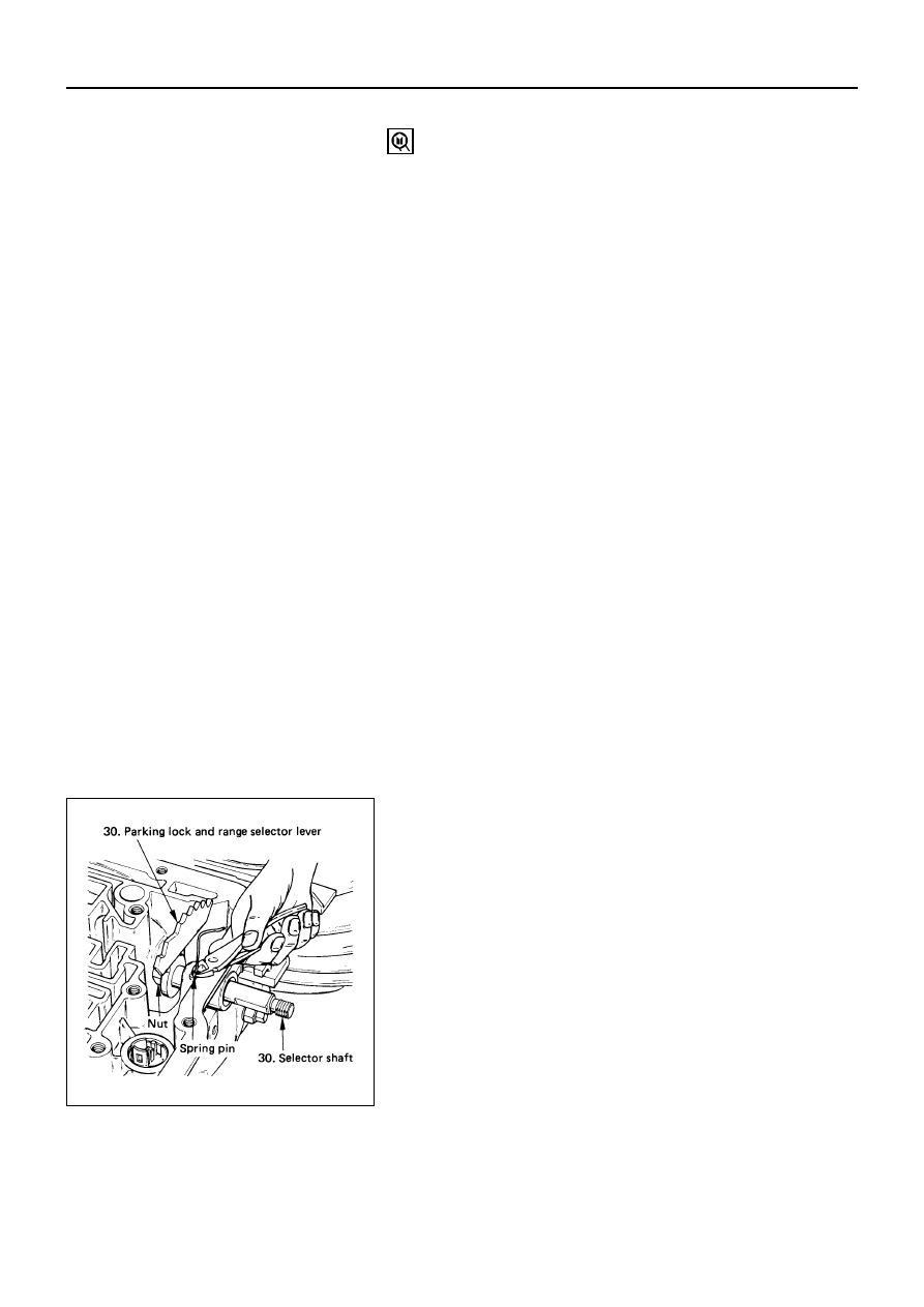
30. Parking Lock and Selector Lever Assembly
1) Rotate case to horizontal position, valve body side
facing up.
2) Remove spring pin, using cutting pliers.
NOTE:
Insert wire in the center of the spring pin to prevent
it from collapsing during removal. Be aware of pin
height. Protect machined face of main case.
3) Remove parking lock and range selector lever 17
mm nut.
4) Remove parking lock and range selector lever and
actuator assembly.
5) Remove selector shaft.
NOTE:
Inspect the shaft for burrs before removing to
prevent damaging seal. If necessary, remove burrs by
lightly sanding with an oilstone.