Isuzu D-Max / Isuzu Rodeo (TFR/TFS). Manual - part 654
 

  Index      Ford     Isuzu D-Max / Isuzu Rodeo TFR/TFS series - service repair manual 1997-2003 year


Search            


Content   ..  652  653  654  655   ..


Isuzu D-Max / Isuzu Rodeo (TFR/TFS). Manual - part 654


7A1–116 AUTOMATIC TRANSMISSION (4L30-E)

DIAGNOSTIC TROUBLE CODE (DTC) 53

MODE SWITCH IN P OR N OR R BAD POSITION

This DTC does NOT flash the CHECK TRANS
indicator and does NOT set the BACKUP MODE.

Circuit Description:

•

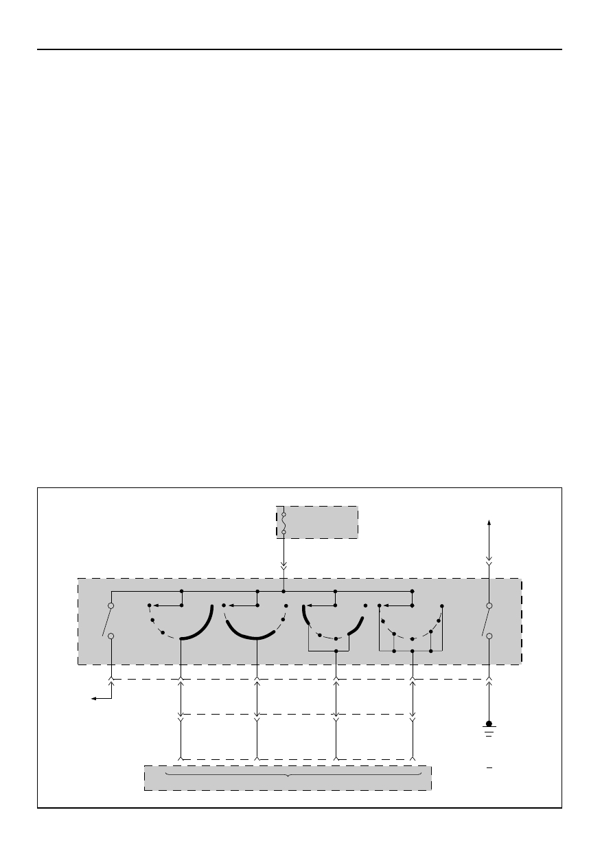
The mode switch supplies the Transmission
Control Module (TCM) with information regard-
ing the selector lever position: P, R, N, D, 3, 2 or
L. The selector lever position is indicated by the
state of four ON/OFF contacts. The mode switch
is located on one side of the transmission. It is on
the transmission manual shaft and is fixed to the
main case.

•

The mode switch is also used to provide the
information P or N to the engine crank wiring.
The engine can be cranked only if connector M-25
terminal 4(H) is connected to terminal 1(E), which
is connected to ground.

•

The mode switch is also used to provide the back
up lamp power in reverse. This is the reason why
the mode switch is supplied through a 15A fuse
(CB-11). This fuse can burn due to short circuit in
the back up lamp.

•

When this fuse is open, the mode switch does
not work and DTC54 is set.

•

The mode position is defined by the shift linkage
which is a link between the shift lever and the
mode switch. A bad adjustment of the shift link-
age can create a mode switch problem (DTC53).

Diagnostic Aids:

•

This Diagnostic is not an electrical test done by

the TCM but a test between different information
(“logic test”).

•

Detection conditions of P or N bad position:
1 A/T Input Speed <3000 RPM
2 TPS > 20%
3 Mode Switch = P or N
4 No malfunction: TPS short to voltage or

ground (DTC 21, DTC22), Engine Speed
(DTC13).

5 The conditions need to be present for at least

4 seconds.

•

Action after the detection time: Default position
assumed for pressure calculation and shift
pattern = always in D.

•

Recovery Conditions: To recover, have the engine
speed higher than 3000 RPM with a TPS higher
than 20% when the mode switch is not in P or N.

•

Detection conditions of R bad position:
1 A/T Output Speed > 3200 RPM (approx. 100 KPH)
2 Mode Switch = R
3 No malfunction: Output speed (DTC11).

Downshift Protection (DTC62).

4 The conditions need to be present for at least

4 seconds.

•

Action after the detection time: Default position
assumed for pressure calculation and shift
pattern = always in D.

•

Recovery conditions: To recover, have the output
speed higher than 3200 RPM when the mode
switch is not R.

AUTOMATIC
TRANSMISSION
MODE
SWITCH

PIN C

CB-11
15A

7(B)

2(F)

6(C)

FUSE BOX

TRANSMISSION CONTROL INPUTS

M-25

5(D)

TRANSMISSION 
CONTROL
MODULE (TCM)

3(G)

4

1

2

3

8(A)

M-25

C-95

1

2

D

3

N

R

P

1

2

D

3

N

R

P

1

2

D

3

N

R

P

1

2

D

3

N

R

P

PIN B

PIN A

PIN G

WHT

BLU/WHT

BLU/RED

BLU

BLU/BLK

BLU/WHT

RED/YEL

BLU/RED

BLU

BLU/BLK

H-23

D5(21)

D6(22)

D7(23)

D4(20)

PIN F

BACK UP
LAMP

PIN E

1(E)

4(H)

M-25

BRN/YEL

STARTER RELAY

BLK

D07LW021

AUTOMATIC TRANSMISSION (4L30-E) 7A1–117

DIAGNOSTIC TROUBLE CODE (DTC) 53

MODE SWITCH IN P OR N OR R BAD POSITION

IF: DTC 23 Throttle Position Sensor (TPS) connector
open or DTC 13 Engine speed, DTC 54 Mode switch
illegal position exists:

YES

GOTO DTC13 or
DTC23 or DTC 54 first.

NO

•

Install scan tool GOTHROUGH TECH2 CONNECTION.

•

Ignition switch ON. Engine running.

•

Selector lever position “P”.

•

Select F0: DATALIST: “TOP SIGNAL” or F0: DATA LIST: “AT INPUT SPEED”.

IF: Display does not change with engine speed or TPS:

YES

DTC 23 or DTC 13 not detected
but are the reason for this 
DTC 53.
GOTO DTC13 or DTC23.

NO

•

Ignition switch ON.

•

Select F0: DATALIST: “SELECTOR POS.”.

•

Move shift selector lever through all positions
and compare results with table 1.

IF: all selector pin displays correct:

NO

YES

The problem is
intermittent. GOTO
INTERMITTENT
CONDITIONS.

•

Check automatic transmission mode switch
adjustment. GOTHROUGH MODE SWITCH
SETTING PROCEDURE (PAGE: 7A1-147)

•

Repair. 

Table 1

Note: “X” indicates TECH2 displays “ACTIVE”.

SHIFT SELECTOR POSITION

TECH1 DISPLAY

P

R

N

D

3

2

L

SELECTOR PIN A

X

X

X

X

SELECTOR PIN B

X

X

X

X

SELECTOR PIN C

X

X

X

X

SELECTOR PIN P

X

X

X

X

7A1–118 AUTOMATIC TRANSMISSION (4L30-E)

DIAGNOSTIC TROUBLE CODE (DTC) 54

MODE SWITCH ILLEGAL POSITION

This DTC flashes the CHECK TRANS indicator and
sets the BACKUP MODE.

Circuit Description:

•

The mode switch supplies the Transmission
Control Module (TCM) with information re-
garding the selector lever position: P, R, N, D, 3, 2
or L. The selector lever position is indicated by
the state of four ON/OFF contacts. The mode
switch is located on one side of the transmission.
It is on the transmission manual shaft and is fixed
to the main case.

•

The mode switch is also used to provide the
information P or N to the engine crank wiring.
The engine can be cranked only if connector M-25
terminal 4(H) is connected to terminal 1(E), which
is connected to ground.

•

The mode switch is also used to provide the back
up lamp power in reverse. This is the reason why
the mode switch is supplied through a 15A fuse
(CB-11). This fuse can burn due to short circuit in
the back up lamp.

•

When this fuse is open, the mode switch does
not work and DTC54 is set.

•

The mode position is defined by the shift linkage
which is a link between the shift lever and the
mode switch. A bad adjustment of the shift
linkage can create a mode switch problem
(DTC53).

Diagnostic Aids:

•

This Diagnostic is an electrical test done by the
TCM.

•

Detection conditions:
1 Selector Pin A and Pin B and Pin C are not

active: no position is identified then.

2 Based upon Table 1, in Park shift selector

position the code is set when Pin A is open or
shorted to ground.

3 The conditions need to be present for at least

5 seconds.

•

Action after the detection time: BACKUP MODE

•

Recovery conditions: To recover, do an IGNITION
CYCLE.

AUTOMATIC
TRANSMISSION
MODE
SWITCH

PIN C

CB-11
15A

7(B)

2(F)

6(C)

FUSE BOX

TRANSMISSION CONTROL INPUTS

M-25

5(D)

TRANSMISSION 
CONTROL
MODULE (TCM)

3(G)

4

1

2

3

8(A)

M-25

C-95

1

2

D

3

N

R

P

1

2

D

3

N

R

P

1

2

D

3

N

R

P

1

2

D

3

N

R

P

PIN B

PIN A

PIN G

WHT

BLU/WHT

BLU/RED

BLU

BLU/BLK

BLU/WHT

RED/YEL

BLU/RED

BLU

BLU/BLK

H-23

D5(21)

D6(22)

D7(23)

D4(20)

PIN F

BACK UP
LAMP

PIN E

1(E)

4(H)

M-25

BRN/YEL

STARTER RELAY

BLK

D07LW021

AUTOMATIC TRANSMISSION (4L30-E) 7A1–119

DIAGNOSTIC TROUBLE CODE (DTC) 54

MODE SWITCH ILLEGAL POSITION

Table 1

Note: “X” indicates TECH2 displays “ACTIVE”.

SHIFT SELECTOR POSITION

TECH1 DISPLAY

P

R

N

D

3

2

L

SELECTOR PIN A

X

X

X

X

SELECTOR PIN B

X

X

X

X

SELECTOR PIN C

X

X

X

X

SELECTOR PIN P

X

X

X

X

•

Install scan tool GOTHROUGH TECH2 CONNECTION.

•

Ignition switch ON. Engine OFF.

•

Selector F0: DATALIST: “SELECTOR POS”.

•

Move shift selector lever through all positions and
compare results with Table 1.

IF: all selector pin displays correct:

YES

NO

The problem is
intermittent. 
GOTO INTERMITTENT
CONDITIONS.

IF: all selector pin displays
incorrect:

YES

NO

•

Check fuse and wire to connector M-25
terminal 5 (D) for opens.
GOTHROUGH MODE SWITCH SETTING
PROCEDURE (PAGE: 7A1-147).
If problem not solved, replace mode
switch.

•

Disconnect mode switch connector M-
25.

•

Connect ohmmeter between terminal
5(D) and respectively all terminals of
mode switch connector M-25.

•

Move shift selector lever through all
positions and compare results with
Table 1.
IF: One selector pin display is incorrect:

NO

YES

•

Check the wire and connector.

•

Repair. 

•

Check wire to cruise control unit and
Transmission Control Module (TCM).

•

Repair. 


Content   ..  652  653  654  655   ..