Isuzu D-Max / Isuzu Rodeo (TFR/TFS). Manual - part 644
 

  Index      Ford     Isuzu D-Max / Isuzu Rodeo TFR/TFS series - service repair manual 1997-2003 year


Search            


Content   ..  642  643  644  645   ..


Isuzu D-Max / Isuzu Rodeo (TFR/TFS). Manual - part 644


7A1–76 AUTOMATIC TRANSMISSION (4L30-E)

DIAGNOSTIC TROUBLE CODE (DTC) 21

THROTTLE POSITION SENSOR SHORT TO PLUS

This DTC flashes the CHECK TRANS indicator and
sets the BACKUP MODE.

Circuit Description:

•

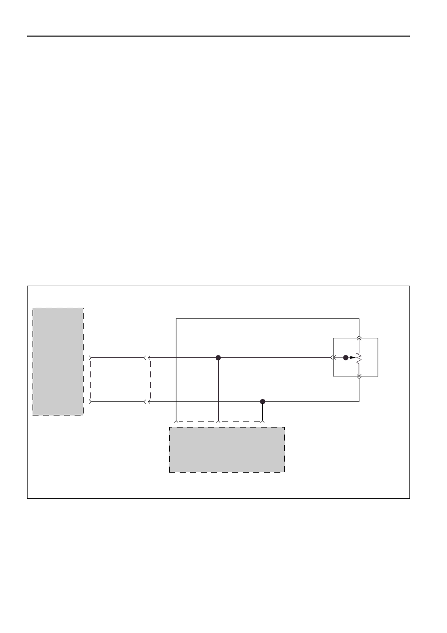
The Throttle Position Sensor (TPS) provides a
voltage signal that changes relative to the throttle
plate position. Signal voltage between connector
C-95 terminals C5 and C6 will vary from about 0.4
at idle to about 4.6 volts at wide open throttle.

•

The Engine Control Module (ECM) also receives
this signal. This TPS is a variable resistance with
one side (connector E-68 terminal 1) connected
only to the ECM connector to have the 5 volts
supply voltage. The other side (connector E-68
terminal 3) is connected to the Transmission
Control Module (TCM) (floating ground) and the
ECM (ground). The “middle” (the wiper) (con-
nector E-68 terminal 2) is connected to the TCM
and the ECM.

•

The ECM monitors output voltage from the TPS
and determines fuel delivery based on throttle
valve angle (driver demand).

•

This TPS is an electrical component and must not
be soaked in any liquid cleaner or solvent, as
damage may result.

Diagnostic Aids:

•

This Diagnostic is an electrical test done by the
TCM.

•

Detection conditions:
1 Voltage between connector C-95 terminals C5

and C6 > 4.9 volts. This detection occurs
when: The wiper is short to voltage (engine
can stall).

2 The condition needs to be present for at least

0.5 seconds. Note: during the detection time
the TCM reads “100% (wide open throttle)”.

•

Action after the detection time: BACKUP MODE.

•

Recovery conditions: To recover when voltage <
or = to 4.9 volts and do an IGNITION CYCLE.

TPS
INPUT

GROUND

TRANSMISSION
CONTROL
MODULE(TCM)

C-95

C5(5)

5

H-25

3

C6(6)

GRN

BLU

BLU

BLU

BLU

GRN

27

5VOLT
REFERENCE

TPS
INPUT

GROUND

GRY

GRY

GRY

THROTTLE
POSITION
SENSOR
(TPS)

ENGINE
CONTROL
MODULE
(ECM)

26

39 E-61

E-68

E-68

E-68

2

1

3

D07LW009

AUTOMATIC TRANSMISSION (4L30-E) 7A1–77

DIAGNOSTIC TROUBLE CODE (DTC) 21

THROTTLE POSITION SENSOR SHORT TO PLUS

Check Engine Control Module (ECM)
DTC.
IF: DTC on Throttle Position Sensor (TPS)
exists:

Check diagnosis of ECM and repair.

•

Connect voltmeter between connector
C-95 terminal C5 and TPS ground
terminal C6.

IF: If you have more than 4.9 volts:

DTC 21 is intermittent.
GOTO INTERMITTENT
CONDITIONS.

GOTO TCM MEM-CAL
REPLACEMENT.

•

Check for a short to voltage or open circuit between connector C-95
terminal C5 and connector E-68 terminal 2.
This faulty connection can be at intermediate connector H-25
terminal 5.
The short to voltage only can be at the ECM connector E-61 terminal
26.

•

Repair.
If not OK: Disconnect sensor.

•

Connect ohmmeter between sensor terminals 2 wiper and 3 low
side.
If resistance between TPS terminal 2 and 3 does not change when
the throttle valve angle is changed: Replace TPS.

YES

NO

YES

NO

NO

YES

•

Install scan tool GOTHROUGH TECH2
CONNECTION.

•

Ignition switch ON, engine not
running.

•

Selector lever position “P”.

•

Select F0: DATA LIST: “TPS SIGNAL”.

IF: TECH2 DISPLAY more than 4.9 volts:

7A1–78 AUTOMATIC TRANSMISSION (4L30-E)

DIAGNOSTIC TROUBLE CODE (DTC) 22

THROTTLE POSITION SENSOR SHORT TO GROUND OR OPEN

This DTC flashes the CHECK TRANS indicator and
sets the BACKUP MODE.

Circuit Description:

•

The Throttle Position Sensor (TPS) provides a
voltage signal that changes relative to the throttle
plate position. Signal voltage between connector
C-95 terminals C5 and C6 will vary from about 0.4
at idle to about 4.6 volts at wide open throttle.

•

The Engine Control Module (ECM) also receives
this signal. This TPS is a variable resistance with
one side (connector E-68 terminal 1) connected
only to the ECM connector to have the 5 volts
supply voltage. The other side (connector E-68
terminal 3) is connected to the Transmission
Control Module (TCM) (floating ground) and the
ECM (ground). The “middle” (the wiper) (con-
nector E-68 terminal 2) is connected to the TCM
and the ECM.

•

The ECM monitors output voltage from the TPS
and determines fuel delivery based on throttle
valve angle (driver demand)

•

This TPS is an electrical component and must not
be soaked in any liquid cleaner or solvent, as
damage may result.

Diagnostic Aids:

•

This Diagnostic is an electrical test done by the
TCM.

•

Detection conditions:

1

This detects a TPS wiper short to TCM ground
(except certain conditions) or open and wiper
short to TPS low. This also detects a TPS low
open.

2

Voltage between connector C-95 terminals C5
and C6 < 0.2 volts. 

3

The condition needs to be present for at least
0.5 seconds. Note: during the detection time
the TCM reads “0% (idle)”.

•

Action after the detection time: BACKUP MODE.

•

Recovery conditions: To recover when voltage >
or = to 0.2 volts and do an IGNITION CYCLE.

TPS
INPUT

GROUND

TRANSMISSION
CONTROL
MODULE(TCM)

C-95

C5(5)

5

H-25

3

C6(6)

GRN

BLU

BLU

BLU

BLU

GRN

27

5VOLT
REFERENCE

TPS
INPUT

GROUND

GRY

GRY

GRY

THROTTLE
POSITION
SENSOR
(TPS)

ENGINE
CONTROL
MODULE
(ECM)

26

39 E-61

E-68

E-68

E-68

2

1

3

D07LW009

AUTOMATIC TRANSMISSION (4L30-E) 7A1–79

DIAGNOSTIC TROUBLE CODE (DTC) 22

THROTTLE POSITION SENSOR SHORT TO GROUND OR OPEN

Check Engine Control Module (ECM)
DTC.
IF: DTC on Throttle Position Sensor (TPS)
exists:

Check diagnosis of ECM and repair. 

•

Install scan tool GOTHROUGH TECH2
CONNECTION.

•

Ignition switch ON, engine not
running.

•

Selector lever position “P”.

•

Select F0: DATA LIST: “TPS SIGNAL”.

IF: TECH2 DISPLAY less than 0.2 volts:

•

Connect voltmeter between connector
C-95 terminal C5 and TPS ground
terminal C6.

IF: If you have less than 0.2 volts:

DTC 22 is intermittent.
GOTO INTERMITTENT
CONDITIONS.

GOTO TCM MEM-CAL
REPLACEMENT.

•

Check for a short to ground between connector C-95 terminal C5 and
connector E-68 terminal 2.
This faulty connection can be at the intermediate connector H-25
terminal 5.This faulty connection can be at the ECM connector E-61
terminal 26.

•

Repair.
If not OK: Ignition switch OFF. Disconnect sensor connector E-68.

•

Connect ohmmeter between connector C-95 terminal C5 and C6.

•

Check if the circuit is open.

•

Repair.
If not OK: Ignition switch OFF. Disconnect sensor connector E-68.

•

Connect ohmmeter between sensor terminals 2 wiper and 3 low
side.

•

If resistance between TPS terminal 2 and 3 does not change when
the throttle valve angle is changed: Replace TPS. 

YES

NO

YES

NO

NO

YES


Content   ..  642  643  644  645   ..